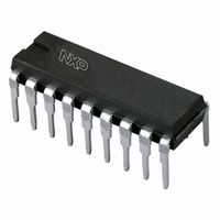
TDA1517P/N3,112 NXP Semiconductors, TDA1517P/N3,112 Datasheet

TDA1517P/N3,112
Specifications of TDA1517P/N3,112
935261850112
TDA1517PN
Related parts for TDA1517P/N3,112
TDA1517P/N3,112 Summary of contents
Page 1
DATA SHEET TDA1517; TDA1517P stereo power amplifier Product specification Supersedes data of 2002 Jan 17 INTEGRATED CIRCUITS 2004 Feb 18 ...
Page 2
... NXP Semiconductors stereo power amplifier FEATURES • Requires very few external components • High output power • Fixed gain • Good ripple rejection • Mute/standby switch • AC and DC short-circuit safe to ground and V • Thermally protected • Reverse polarity safe • Capability to handle high energy on outputs (V • ...
Page 3
... NXP Semiconductors stereo power amplifier BLOCK DIAGRAM handbook, full pagewidth non-inverting 1 input 1 supply voltage 3 ripple rejection output non-inverting 9 input 2 reference 2004 Feb 18 mute switch kΩ kΩ 18 kΩ stand-by switch VA 15 kΩ kΩ mute reference voltage 18 kΩ 2 kΩ kΩ ...
Page 4
... NXP Semiconductors stereo power amplifier PINNING SYMBOL −INV1 SGND SVRR OUT1 PGND OUT2 V P M/SS −INV2 handbook, halfpage INV1 1 SGND 2 SVRR 3 OUT1 4 PGND 5 TDA1517 OUT2 M/SS 8 INV2 9 Fig.2 Pin configuration for SOT110-1 and SOT352-1. FUNCTIONAL DESCRIPTION The TDA1517 contains two identical amplifiers with differential input stages ...
Page 5
... NXP Semiconductors stereo power amplifier LIMITING VALUES In accordance with the Absolute Maximum Rating System (IEC 60134). SYMBOL PARAMETER V supply voltage and DC short-circuit safe voltage P(sc) V reverse polarity P(r) ERG energy handling capability at outputs O I non-repetitive peak output current OSM I repetitive peak output current ...
Page 6
... NXP Semiconductors stereo power amplifier DC CHARACTERISTICS = 25 °C; measured in Fig.6; unless otherwise specified 14 amb SYMBOL PARAMETER Supply V supply voltage P I total quiescent current q(tot output voltage O Mute/standby switch V switch-on voltage level 8 Mute condition V output signal in mute position O Standby condition I DC current in standby condition ...
Page 7
... NXP Semiconductors stereo power amplifier AC CHARACTERISTICS = 4 Ω kHz 14 SYMBOL PARAMETER P output power o THD total harmonic distortion f low frequency roll-off lr f high frequency roll-off hr G closed loop voltage gain v SVRR supply voltage ripple rejection on mute standby |Z | input impedance i V noise output voltage ...
Page 8
... NXP Semiconductors stereo power amplifier handbook, halfpage ( mA) P 8.5 6.4 mute ( mA) P 3.3 2 standby ( Fig.5 Standby, mute and on conditions. APPLICATION INFORMATION handbook, full pagewidth 220 nF input 1 2004 Feb 18 MLC355 100 μA) 100 μF 3 input internal reference 1 voltage TDA1517 kΩ 1000 μF ...
Page 9
... NXP Semiconductors stereo power amplifier PACKAGE OUTLINES SIL9MPF: plastic single in-line medium power package with fin; 9 leads P pin 1 index DIMENSIONS (mm are the original dimensions UNIT max. 18.5 8.7 15.8 1.40 mm 3.7 17.8 8.0 15.4 1.14 Note 1. Plastic or metal protrusions of 0.25 mm maximum per side are not included. ...
Page 10
... NXP Semiconductors stereo power amplifier RBS9MPF: plastic rectangular-bent single in-line medium power package with fin; 9 leads pin 1 index DIMENSIONS (mm are the original dimensions) A (1) 2 UNIT max. 14.45 8.7 1.40 0.67 mm 3.7 13.95 8.0 1.14 0.50 Notes 1. Dimension is specified at seating plane. 2. Plastic or metal protrusions of 0.25 mm maximum per side are not included. ...
Page 11
... NXP Semiconductors stereo power amplifier HDIP18: plastic heat-dissipating dual in-line package; 18 leads pin 1 index 1 DIMENSIONS (inch dimensions are derived from the original mm dimensions UNIT max. min. max. mm 4.7 0.51 3.7 inches 0.19 0.02 0.15 Note 1. Plastic or metal protrusions of 0.25 mm (0.01 inch) maximum per side are not included. ...
Page 12
... NXP Semiconductors stereo power amplifier SOLDERING Introduction to soldering through-hole mount packages This text gives a brief insight to wave, dip and manual soldering. A more in-depth account of soldering ICs can be found in our “Data Handbook IC26; Integrated Circuit Packages” (document order number 9398 652 90011). ...
Page 13
... In no event shall NXP Semiconductors be liable for any indirect, incidental, punitive, special or consequential damages (including - without limitation - lost profits, lost savings, business interruption, costs related to the ...
Page 14
... NXP Semiconductors’ specifications such use shall be solely at customer’s own risk, and (c) customer fully indemnifies NXP Semiconductors for any liability, damages or failed product claims resulting from customer design and use of the product for automotive applications beyond NXP Semiconductors’ ...
Page 15
... RF, Analog, Power Management, Interface, Security and Digital Processing expertise Customer notification This data sheet was changed to reflect the new company name NXP Semiconductors. No changes were made to the content, except for the legal definitions and disclaimers. Contact information For additional information please visit: http://www ...


