TDA2003H STMicroelectronics, TDA2003H Datasheet
TDA2003H
Specifications of TDA2003H
Available stocks


Related parts for TDA2003H


TDA2003H Summary of contents
Page 1
DESCRIPTION The TDA 2003 has improved performance with the same pin configuration as the TDA 2002. The additional features of TDA 2002, very low number of external components, ease of assembly, space and cost saving, are maintained. The device ...
Page 2
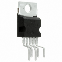
TDA2003 PIN CONNECTION (top view) SCHEMATIC DIAGRAM THERMAL DATA Symbol R Thermal resistance junction-case th-j-case 2/10 Parameter Value Unit max 3 C/W ...
Page 3
DC TEST CIRCUIT ELECTRICAL CHARACTERISTICS ( V Symbol Parameter DC CHARACTERISTICS (Refer to DC test circuit) V Supply voltage s V Quiescent output voltage (pin Quiescent drain current (pin CHARACTERISTICS (Refer to AC test ...
Page 4
TDA2003 ELECTRICAL CHARACTERISTICS (continued) Symbol Parameter B Frequency response (-3 dB) d Distortion R Input resistance (pin Voltage gain (open loop Voltage gain (closed loop Input noise voltage N i Input noise current ...
Page 5
Figure 4. Output power vs. load resistance ure 7. Di stortion vs. output power Figure 10. Supply voltage rejection vs. frequency Figure 5. Gain vs. input sensivity Fi gure 8. Distor tion vs. frequency Figure 11. ...
Page 6
TDA2003 Figure 13. Maximum power dissipation vs. supply voltage (sine wave operation) APPLICATION INFORMATION Figure 16. Typical application circuit BUILT-IN PROTECTION SYSTEMS Load dump voltage surge The TDA 2003 has a circuit which enables it to withstand a voltage pulse ...
Page 7
Figure 18. Short-circuit (AC and DC conditions) The TDA 2003 can withstand a permanent short- circuit on the output for a supply voltage up to 16V. Polarity inversion High current (up to 5A) can be handled by the device with ...
Page 8
TDA2003 PRATICAL CONSIDERATION Printed circuit board The layout shown in fig recommended. If different layouts are used, the ground points of input 1 and input 2 must be well decoupled from the ground of the output through which ...
Page 9
DIM. MIN. TYP. MAX. MIN. A 4.8 C 1.37 D 2.4 2.8 0.094 D1 1.2 1.35 0.047 E 0.35 0.55 0.014 E1 0.76 1.19 0.030 F 0.8 1.05 0.031 F1 1 1.4 0.039 G 3.2 3.4 3.6 0.126 G1 ...
Page 10
... No license is granted by implication or otherwise under any patent or patent rights of STMicroelectronics. Specification mentioned in this publication are subject to change without notice. This publication supersedes and replaces all information previously supplied. STMicroelectronics products are not authorized for use as critical components in life support devices or systems without express written approval of STMicroelectronics. © ...