TDA2052V STMicroelectronics, TDA2052V Datasheet
TDA2052V
Specifications of TDA2052V
Available stocks


Related parts for TDA2052V


TDA2052V Summary of contents
Page 1
... This is advanced information on a new product now in development or undergoing evaluation. Details are subject to change without notice. 60W Hi-Fi AUDIO POWER AMPLIFIER WITH MUTE / STAND-BY Heptawatt V ORDERING NUMBERS: TDA2052V est power into both 4 presence of poor supply regulation. The built in Muting/Stand-by function simplifies the remote operations avoiding also switching on- off noises ...
Page 2
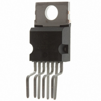
TDA2052 ABSOLUTE MAXIMUM RATINGS Symbol V DC Supply Voltage S I Output Peak Current (internally limited Power Dissipation T tot T Operating Temperature Range Storage and Junction Temperature stg j PIN CONNECTION (Top view) ...
Page 3
THERMAL DATA Symbol R Thermal Resistance Junction-case th j-case ELECTRICAL CHARACTERISTICS (Refer to the test circuit unless otherwise specified.) Symbol Parameter V Supply Range S I Total Quiescent Current q I Input Bias Current b V Input ...
Page 4
TDA2052 APPLICATIONS SUGGESTIONS (See Test and Application Circuit) The recommended values of the external components are those shown on the application circuit. Differ- ent values can be used; the following table can help the designer. Comp. Value R1 22K (*) ...
Page 5
Figure 3: Output Power vs. Supply Voltage. Figure 5: Distortion vs. Frequency. Figure 7: Quiescent Current vs. Supply Voltage Figure 4: Distortion vs. Output Power. Figure 6: Distortion vs. Frequency. Figure 8: Supply Voltage Rejection vs. Frequency. TDA2052 5/14 ...
Page 6
TDA2052 Figure 9: Bandwidth. Figure 11: Total Power Dissipation & Efficiency vs. Output Power. 6/14 Figure 10: Output Attenuation & Quiescent Cur- rent vs pin3 Figure 12: Total Power Dissipation & Efficiency vs. Output Power. ...
Page 7
Figure 13: P.C. Board and Components Layout of the Circuit of Fig. 14 (1:1 scale) Figure 14: Demo Board Schematic. TDA2052 7/14 ...
Page 8
TDA2052 MUTE/STAND-BY FUNCTION The pin 3 (MUTE/STAND-BY) controls the ampli- fier status by three different thresholds, referred When its voltage is lower than the first threshold (1V, with a +70mV hysteresis), the amplifier is in STAND-BY ...
Page 9
SHORT-CIRCUIT PROTECTION The TDA 2052 has an original circuit which pro- tects the device during accidental short-circuit be- tween output and GND / -Vs / +Vs, taking it in STAND-BY mode, so limiting also dangerous DC current flowing throught the ...
Page 10
TDA2052 APPLICATION NOTES 90W MULTIWAY SPEAKER SYSTEM The schematic diagram of figure 18, shows the solution that we have closen as a suggestion for Hi-Fi and especially TV applications. The multiway system provides the separation of the musical signal not ...
Page 11
As shown in Figure 19, the R-C passive network for low-pass and High-pass give a cut with a slope of 12dB/octave A further advantage of this application is that con- necting each speaker direcly to its amplifier, the musical signal ...
Page 12
TDA2052 mm DIM. MIN. TYP. MAX. A 4.8 C 1.37 D 2.4 2.8 0.094 D1 1.2 1.35 0.047 E 0.35 0.55 0.014 E1 0.7 0.97 0.028 F 0.6 0.8 0.024 G 2.34 2.54 2.74 0.095 G1 4.88 5.08 5.28 0.193 ...
Page 13
DIM. MIN. TYP. MAX. MIN. A 4.80 C 1.37 D 2.40 2.80 0.094 D1 1.20 1.35 0.047 E 0.35 0.55 0.014 E1 0.70 0.97 0.03 F 0.60 0.80 0.024 G 2.34 2.54 2.74 0.092 G1 4.88 5.08 5.28 0.192 ...
Page 14
... This publication supersedes and replaces all information previously supplied. STMicroelectronics products are not authorized for use as critical components in life support devices or systems without express written approval of STMicroelectronics. © 2003 STMicroelectronics – Printed in Italy – All Rights Reserved Australia - Brazil - Canada - China - Finland - France - Germany - Hong Kong - India - Israel - Italy - Japan - Malaysia - Malta - Morocco - Singapore - Spain - Sweden - Switzerland - United Kingdom - United States ...