LM48555TL/NOPB National Semiconductor, LM48555TL/NOPB Datasheet - Page 10
LM48555TL/NOPB
Manufacturer Part Number
LM48555TL/NOPB
Description
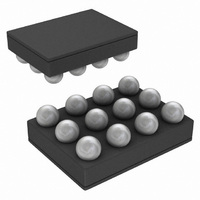
IC AMP AUDIO PWR MONO AB 12USMD
Manufacturer
National Semiconductor
Series
Boomer®r
Type
Class ABr
Datasheet
1.LM48555TLNOPB.pdf
(14 pages)
Specifications of LM48555TL/NOPB
Output Type
1-Channel (Mono)
Voltage - Supply
2.7 V ~ 9 V
Features
Depop, Differential Inputs, Shutdown
Mounting Type
Surface Mount
Package / Case
12-MicroSMD
For Use With
LM48555TLBD - BOARD EVALUATION LM48555TL
Lead Free Status / RoHS Status
Lead free / RoHS Compliant
Max Output Power X Channels @ Load
-
Other names
LM48555TLTR


www.national.com
OUTPUT VOLTAGE OF BOOST CONVERTER
The output voltage is set using two internal resistors. The
output voltage of the boost converter is set to 8V (typ).
DUTY CYCLE
The maximum duty cycle of the boost converter determines
the maximum boost ratio of output-to-input voltage that the
converter can attain in continuous mode of operation. The
duty cycle for a given boost application is defined by equation
7:
This applies for continuous mode operation.
INDUCTANCE VALUE
Inductor value involves trade-offs in performance. Larger in-
ductors reduce inductor ripple current, which typically means
less output voltage ripple (for a given size of output capacitor).
Larger inductors also mean more load power can be delivered
because the energy stored during each switching cycle is:
Where “lp” is the peak inductor current. The LM48555 will limit
its switch current based on peak current. With I
creasing L will increase the maximum amount of power avail-
able to the load. Conversely, using too little inductance may
limit the amount of load current which can be drawn from the
output. Best performance is usually obtained when the con-
verter is operated in “continuous” mode at the load current
range of interest, typically giving better load regulation and
less output ripple. Continuous operation is defined as not al-
lowing the inductor current to drop to zero during the cycle.
Boost converters shift over to discontinuous operation if the
load is reduced far enough, but a larger inductor stays con-
tinuous over a wider load current range.
INDUCTOR SUPPLIERS
The recommended inductors for the LM48555 are the Taiyo-
Yuden NR4012, NR3010, and CBC3225 series and Murata's
LQH3NPN series. When selecting an inductor, the continu-
ous current rating must be high enough to avoid saturation at
peak currents. A suitable core type must be used to minimize
Duty Cycle = (V
AMP
+V
E = L/2 x I
DIODE
-V
DD
P
2
)/(V
AMP
+V
DIODE
-V
P
SW
fixed, in-
)
(7)
(8)
10
core (switching) losses, and wire power losses must be con-
sidered when selecting the current rating.
CALCULATING OUTPUT CURRENT OF BOOST
CONVERTER (I
The load current of the boost converter is related to the av-
erage inductor current by the relation:
Where "DC" is the duty cycle of the application.
The switch current can be found by:
Inductor ripple current is dependent on inductance, duty cy-
cle, supply voltage and frequency:
where f = switching frequency = 1MHz
combining all terms, we can develop an expression which al-
lows the maximum available load current to be calculated:
The equation shown to calculate maximum load current takes
into account the losses in the inductor or turn-off switching
losses of the FET and diode.
DESIGN PARAMETERS V
The value of the FET "ON" voltage (referred to as V
equations 9 thru 12) is dependent on load current. A good
approximation can be obtained by multiplying the on resis-
tance (R
The maximum peak switch current the device can deliver is
dependent on duty cycle.
EVALUATION BOARD AND PCB LAYOUT GUIDELINES
For information on the LM48555 demo board and PCB layout
guidelines refer to Application Notes (AN-1611).
I
AMP(max)
I
DS(ON)
SW
I
RIPPLE
I
AMP
= (1–DC)x[I
= I
= I
INDUCTOR(AVE)
of the FET times the average inductor current.
= DC x (V
AMP
INDUCTOR(AVE)
)
SW(max)
DD
SW
-V
+ 1/2 (I
AND I
SW
–DC(V-V
x (1 - DC) (A)
) / (f x L) (A)
RIPPLE
SW
SW
) (A)
)]/2fL (A)
SW
(10)
(11)
(12)
(9)
in
Related parts for LM48555TL/NOPB
Image
Part Number
Description
Manufacturer
Datasheet
Request
R

Part Number:
Description:
National Semiconductor [8-Bit D/A Converter]
Manufacturer:
National Semiconductor
Datasheet:
Part Number:
Description:
National Semiconductor [Media Coprocessor]
Manufacturer:
National Semiconductor
Datasheet:
Part Number:
Description:
Digitally Controlled Tone and Volume Circuit with Stereo Audio Power Amplifier, Microphone Preamp Stage and National 3D Sound
Manufacturer:
National Semiconductor
Datasheet:
Part Number:
Description:
Digitally Controlled Tone and Volume Circuit with Stereo Audio Power Amplifier, Microphone Preamp Stage and National 3D Sound
Manufacturer:
National Semiconductor
Datasheet:
Part Number:
Description:
AC97 Rev 2 Codec with Sample Rate Conversion and National 3D Sound
Manufacturer:
National Semiconductor
Part Number:
Description:
Manufacturer:
National Semiconductor
Datasheet:
Part Number:
Description:
Manufacturer:
National Semiconductor
Datasheet:
Part Number:
Description:
General Purpose, Low Voltage, Low Power, Rail-to-Rail Output Operational Amplifiers
Manufacturer:
National Semiconductor
Datasheet:
Part Number:
Description:
8-bit 20 MSPS flash A/D converter.
Manufacturer:
National Semiconductor
Datasheet:
Part Number:
Description:
Low Noise Quad Operational Amplifier
Manufacturer:
National Semiconductor
Datasheet:
Part Number:
Description:
Quad Differential Line Receivers
Manufacturer:
National Semiconductor
Datasheet:
Part Number:
Description:
Quad High Speed Trapezoidal? Bus Transceiver
Manufacturer:
National Semiconductor
Datasheet:
Part Number:
Description:
Dual Line Receiver
Manufacturer:
National Semiconductor
Datasheet:
Part Number:
Description:
TTL to 10k ECL Level Translator with Latch
Manufacturer:
National Semiconductor
Datasheet: