LM48555TL/NOPB National Semiconductor, LM48555TL/NOPB Datasheet - Page 9
LM48555TL/NOPB
Manufacturer Part Number
LM48555TL/NOPB
Description
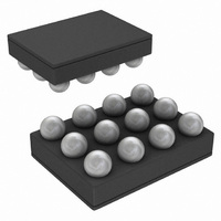
IC AMP AUDIO PWR MONO AB 12USMD
Manufacturer
National Semiconductor
Series
Boomer®r
Type
Class ABr
Datasheet
1.LM48555TLNOPB.pdf
(14 pages)
Specifications of LM48555TL/NOPB
Output Type
1-Channel (Mono)
Voltage - Supply
2.7 V ~ 9 V
Features
Depop, Differential Inputs, Shutdown
Mounting Type
Surface Mount
Package / Case
12-MicroSMD
For Use With
LM48555TLBD - BOARD EVALUATION LM48555TL
Lead Free Status / RoHS Status
Lead free / RoHS Compliant
Max Output Power X Channels @ Load
-
Other names
LM48555TLTR


quick, smooth transition into shutdown. Another solution is to
use a single-pole, single-throw switch connected between
V
BOOTSTRAP PIN
The bootstrap pin provides a voltage supply for the internal
switch driver. Connecting the bootstrap pin to VAMP (See
Figure 1) allows for a higher voltage to drive the gate of the
switch thereby reducing the R
necessary in applications with heavier loads. The bootstrap
pin can be connected to V
prove device performance (I
PROPER SELECTION OF EXTERNAL COMPONENTS
Proper selection of external components in applications using
integrated power amplifiers, and switching DC-DC convert-
ers, is critical for optimizing device and system performance.
Consideration to component values must be used to maxi-
mize overall system quality. The best capacitors for use with
the switching converter portion of the LM48555 are multi-layer
ceramic capacitors. They have the lowest ESR (equivalent
series resistance) and highest resonance frequency, which
makes them optimum for high frequency switching convert-
ers. When selecting a ceramic capacitor, only X5R and X7R
dielectric types should be used. Other types such as Z5U and
Y5F have such severe loss of capacitance due to effects of
temperature variation and applied voltage, they may provide
as little as 20% of rated capacitance in many typical applica-
tions. Always consult capacitor manufacturer’s data curves
before selecting a capacitor. High-quality ceramic capacitors
can be obtained from Taiyo-Yuden and Murata.
POWER SUPPLY BYPASSING
As with any amplifier, proper supply bypassing is critical for
low noise performance and high power supply rejection. The
capacitor location on both V1 and V
to the device as possible.
SELECTING INPUT AND FEEDBACK CAPACITORS AND
RESISTOR FOR AUDIO AMPLIFIER
Special care must be taken to match the values of the feed-
back resistors (RF+ and RF-) to each other as well as match-
ing the input resistors (RIN+ and RIN-) to each other (see
Figure 1). Because of the balanced nature of differential am-
plifiers, resistor matching differences can result in net DC
currents across the load. This DC current can increase power
consumption, internal IC power dissipation, reduce PSRR,
and possibly damage the loudspeaker. To achieve best per-
formance with minimum component count, it is highly recom-
mended that both the feedback and input resistors match to
1% tolerance or better.
The input coupling capacitors, CIN, forms a first order high
pass filter which limits low frequency response. This value
should be chosen based on needed frequency response.
High value input capacitors are both expensive and space
hungry in portable designs. A certain value capacitor is need-
ed to couple in low frequencies without severe attenuation.
Ceramic speakers used in portable systems, whether internal
or external, have little ability to reproduce signals below
100Hz to 150Hz. Thus, using a high value input capacitor may
not increase actual system performance. In addition to sys-
tem cost and size, click and pop performance is affected by
the value of the input coupling capacitor, CIN. A high value
input coupling capacitor requires more charge to reach its
quiescent DC voltage (nominally 1/2 V
from the output via the feedback and is apt to create pops
upon device enable. Thus, by minimizing the capacitor value
DD
and Shutdown pins.
DD
DD
when driving lighter loads to im-
, THD+N, Noise, etc.).
DS(ON)
DD
DD
. This configuration is
pins should be as close
). This charge comes
9
based on desired low frequency response, turn-on pops can
be minimized.
The LM48555 is unity-gain stable which gives the designer
maximum system flexibility. However, to drive ceramic speak-
ers, a typical application requires a closed-loop differential
gain of 10V/V. In this case, feedback capacitors (CF+, CF-)
may be needed as shown in Figure 1 to bandwidth limit the
amplifier. If the available input signal is bandwith limited, then
capacitors CF+ and CF- can be eliminated. These feedback
capacitors create a low pass filter that eliminates possible
high frequency noise. Care should be taken when calculating
the -3dB frequency (from equation 6) because an incorrect
combination of RF and CF will cause rolloff before the desired
frequency.
SELECTING OUTPUT CAPACITOR (CO) FOR BOOST
CONVERTER
A single 4.7μF to 10μF ceramic capacitor will provide suffi-
cient output capacitance for most applications. If larger
amounts of capacitance are desired for improved line support
and transient response, tantalum capacitors can be used.
Aluminum electrolytics with ultra low ESR such as Sanyo Os-
con can be used. Typical electrolytic capacitors are not suit-
able for switching frequencies above 500 kHz because of
significant ringing and temperature rise due to self-heating
from ripple current. An output capacitor with excessive ESR
can also reduce phase margin and cause instability. In gen-
eral, if electrolytics are used, it is recommended that they be
paralleled with ceramic capacitors to reduce ringing, switch-
ing losses, and output voltage ripple.
SELECTING A POWER SUPPLY BYPASS CAPACITOR
A supply bypass capacitor is required to serve as an energy
reservoir for the current which must flow into the coil each time
the switch turns on. This capacitor must have extremely low
ESR, so ceramic capacitors are the best choice. A nominal
value of 4.7μF is recommended, but larger values can be
used. Since this capacitor reduces the amount of voltage rip-
ple seen at the input pin, it also reduces the amount of EMI
passed back along that line to other circuitry.
SELECTING A SOFT-START CAPACITOR (CSS)
The soft-start function charges the boost converter reference
voltage slowly. This allows the output of the boost converter
to ramp up slowly thus limiting the transient current at startup.
Selecting a soft-start capacitor (CSS) value presents a trade
off between the wake-up time and the startup transient cur-
rent. Using a larger capacitor value will increase wake-up time
and decrease startup transient current while the apposite ef-
fect happens with a smaller capacitor value. A general guide-
line is to use a capacitor value 1000 times smaller than the
output capacitance of the boost converter (CO). A 0.1uF soft-
start capacitor is recommended for a typical application.
SELECTING DIODES
The external diode used in Figure 1 should be a Schottky
diode. A 20V diode such as the MBR0520 from Fairchild
Semiconductor or ON Semiconductor is recommended. The
MBR05XX series of diodes are designed to handle a maxi-
mum average current of 0.5A. For applications exceeding
0.5A average but less than 1A, a Microsemi UPS5817 can be
used.
f
–3dB
= 1 / 2πRF*CF
www.national.com
(6)
Related parts for LM48555TL/NOPB
Image
Part Number
Description
Manufacturer
Datasheet
Request
R

Part Number:
Description:
National Semiconductor [8-Bit D/A Converter]
Manufacturer:
National Semiconductor
Datasheet:
Part Number:
Description:
National Semiconductor [Media Coprocessor]
Manufacturer:
National Semiconductor
Datasheet:
Part Number:
Description:
Digitally Controlled Tone and Volume Circuit with Stereo Audio Power Amplifier, Microphone Preamp Stage and National 3D Sound
Manufacturer:
National Semiconductor
Datasheet:
Part Number:
Description:
Digitally Controlled Tone and Volume Circuit with Stereo Audio Power Amplifier, Microphone Preamp Stage and National 3D Sound
Manufacturer:
National Semiconductor
Datasheet:
Part Number:
Description:
AC97 Rev 2 Codec with Sample Rate Conversion and National 3D Sound
Manufacturer:
National Semiconductor
Part Number:
Description:
Manufacturer:
National Semiconductor
Datasheet:
Part Number:
Description:
Manufacturer:
National Semiconductor
Datasheet:
Part Number:
Description:
General Purpose, Low Voltage, Low Power, Rail-to-Rail Output Operational Amplifiers
Manufacturer:
National Semiconductor
Datasheet:
Part Number:
Description:
8-bit 20 MSPS flash A/D converter.
Manufacturer:
National Semiconductor
Datasheet:
Part Number:
Description:
Low Noise Quad Operational Amplifier
Manufacturer:
National Semiconductor
Datasheet:
Part Number:
Description:
Quad Differential Line Receivers
Manufacturer:
National Semiconductor
Datasheet:
Part Number:
Description:
Quad High Speed Trapezoidal? Bus Transceiver
Manufacturer:
National Semiconductor
Datasheet:
Part Number:
Description:
Dual Line Receiver
Manufacturer:
National Semiconductor
Datasheet:
Part Number:
Description:
TTL to 10k ECL Level Translator with Latch
Manufacturer:
National Semiconductor
Datasheet: