XPSAC5121P Crouzet USA, XPSAC5121P Datasheet - Page 111
XPSAC5121P
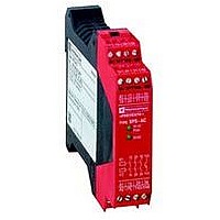
Manufacturer Part Number
XPSAC5121P
Description
89H6659
Manufacturer
Crouzet USA
Datasheet
1.XPSMCCPC.pdf
(274 pages)
Specifications of XPSAC5121P
Contact Current Max
40mA
Contact Voltage Ac Nom
24V
Contact Voltage Dc Nom
24V
Contact Configuration
3PST-NO
Relay Mounting
DIN Rail
External Height
66mm
External Width
114mm
External Depth
22.5mm
Rohs Compliant
No


10
10
1
1
2
2
3
3
4
4
5
5
6
6
7
7
8
8
9
9
Wiring diagrams
Configuration 1 (1-channel Emergency stop, automatic or unmonitored start) = function 1.
Configuration 2 (1-channel Emergency stop, monitored start) = function 2.
(1) Automatic start.
(2) Function 1 safety outputs.
Configuration 1
Automatic start
Key
Input 1, Emergency stop
C1-I1, (C4-I4)
Input 2, ESC C2-I2,
(C5-I5)
Automatic start C3-I3,
(C6-I6)
N.O. output 13-14/23-24/
33-34, (43-44/53-54/63-64)
Signalling output Y84,
(Y94)
Configuration 2
Monitored start
Key
Input 1, Emergency stop
C1-I1, (C4-I4)
Input 2, ESC C2-I2,
(C5-I5)
Start button C3-I3,
(C6-I6)
N.O. output 13-14/23-24/
33-34, (43-44/53-54/63-64)
Signalling output Y84,
(Y94)
Presentation:
page 2/106
2/110
XPSMP
Emergency stop monitoring, 1-channel wiring
Functional diagrams
+
0 V
24 V
F1
0
0
A2
A1
C3
C6
1
1
C2
C5
Power-up (Self-test accomplished)
Power-up (Self-test accomplished)
Emergency stop
not activated
Emergency stop
not activated
C1
C4
Emergency
stop 1 F2
Emergency
stop 2 F2
Emergency
stop F1
Logic
channel 1
Logic
channel 2
Characteristics:
page 2/107
S1
S4.2
S4.1
Emergency
stop
activated
Emergency
stop
activated
I1
I4
ESC
F1
ESC
F2
K11
K12
K02
K02
Function 1
Function 2
Function 1
Function 2
I2
I5
(F2)
(F1)
(F2)
(F1)
Emergency stop
not activated
Emergency stop
not activated
Start
S3
K3
K4
Start
F1
K2
K1
Safety automation system solutions
Preventa™ safety controllers type XPSMP
With pre-defined functions
References:
page 2/108
F2
I3
I6
S6
Function 1 Function 1
(1)
K11
13
14
(3) Function 2 safety outputs.
ESC = External start conditions.
Configuration 1
Unmonitored start
Key
Input 1, Emergency stop
C1-I1, (C4-I4)
Input 2, ESC C2-I2,
(C5-I5)
Start button C3-I3,
(C6-I6)
N.O. output 13-14/23-24/
33-34, (43-44/53-54/63-64)
Signalling output Y84,
(Y94)
24
23
K12
(2)
0
33
34
Function 2 Function 2
Dimensions:
page 2/109
K21
1
44
43
Power-up (Self-test accomplished)
Emergency stop
not activated
53
54
K22
(3)
63
64
Y
+
Emergency
stop activated
Y74
XPS MP
Wiring Diagrams:
page 2/110 to 2/117
Y84
Emergency stop
not activated
Y94
To PLC
Related parts for XPSAC5121P
Image
Part Number
Description
Manufacturer
Datasheet
Request
R

Part Number:
Description:
SCREW SOCKET (OT08PC)
Manufacturer:
Crouzet USA
Datasheet:

Part Number:
Description:
PANEL PLATE FOR 813
Manufacturer:
Crouzet USA
Datasheet:
Part Number:
Description:
Controller; CTD46 Dual Display Temperature, 1/16 DIN, NEMA 4X, 110/220VAC
Manufacturer:
Crouzet USA
Datasheet:

Part Number:
Description:
11R1084
Manufacturer:
Crouzet USA
Datasheet:
Part Number:
Description:
11R1086
Manufacturer:
Crouzet USA
Datasheet:
Part Number:
Description:
11R1087
Manufacturer:
Crouzet USA
Datasheet:
Part Number:
Description:
11R1089
Manufacturer:
Crouzet USA
Datasheet:
Part Number:
Description:
11R1078
Manufacturer:
Crouzet USA
Datasheet:
Part Number:
Description:
11R1079
Manufacturer:
Crouzet USA
Datasheet: