BA5417 Rohm Semiconductor, BA5417 Datasheet - Page 9
BA5417
Manufacturer Part Number
BA5417
Description
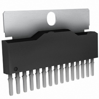
IC AMP AUDIO 5W STER AB 15SIP
Manufacturer
Rohm Semiconductor
Type
Class ABr
Specifications of BA5417
Output Type
2-Channel (Stereo)
Max Output Power X Channels @ Load
5W x 2 @ 3 Ohm
Voltage - Supply
6 V ~ 15 V
Features
Depop, Standby, Thermal Protection
Mounting Type
Through Hole
Package / Case
15-SIP + Tab
No. Of Channels
2
Output Power
5W
Supply Voltage Range
6V To 15V
Thd + N
0.1% @ 500mW, 3ohm, VDD=9V
Load Impedance
3ohm
Operating Temperature Range
-20°C To +75°C
Amplifier Case Style
SIP
Rohs Compliant
Yes
Lead Free Status / RoHS Status
Lead free / RoHS Compliant
Available stocks
Company
Part Number
Manufacturer
Quantity
Price
Company:

Part Number:
BA5417
Manufacturer:
ROHM
Quantity:
5 510
Part Number:
BA5417
Manufacturer:
ROHM/罗姆
Quantity:
20 000


●Notes for use
BA5406,BA5417
© 2010 ROHM Co., Ltd. All rights reserved.
www.rohm.com
1) Numbers and data in entries are representative design values and are not guaranteed values of the items.
2) Although ROHM is confident that the example application circuit reflects the best possible recommendations, be sure to
3) Absolute maximum ratings
4) GND potential
5) Thermal design
6) Short circuit between terminals and erroneous mounting
7) Operation in strong electromagnetic field
verify circuit characteristics for your particular application. Modification of constants for other externally connected circuits
may cause variations in both static and transient characteristics for external components as well as this Rohm IC. Allow for
sufficient margins when determining circuit constants.
Use of the IC in excess of absolute maximum ratings, such as the applied voltage or operating temperature range (Topr),
may result in IC damage. Assumptions should not be made regarding the state of the IC (short mode or open mode) when
such damage is suffered. A physical safety measure, such as a fuse, should be implemented when using the IC at times
where the absolute maximum ratings may be exceeded.
Ensure a minimum GND pin potential in all operating conditions. Make sure that no pins are at a voltage below the GND at
any time, regardless of whether it is a transient signal or not.
Perform thermal design, in which there are adequate margins, by taking into account the permissible dissipation (Pd) in
actual states of use.
Pay attention to the assembly direction of the ICs. Wrong mounting direction or shorts between terminals, GND, or other
components on the circuits, can damage the IC.
Using the ICs in a strong electromagnetic field can cause operation malfunction.
9/10
Technical Note
2010.11 - Rev.B
Related parts for BA5417
Image
Part Number
Description
Manufacturer
Datasheet
Request
R

Part Number:
Description:
Manufacturer:
Rohm Semiconductor
Datasheet:
Part Number:
Description:
Manufacturer:
Rohm Semiconductor
Datasheet:
Part Number:
Description:
Manufacturer:
Rohm Semiconductor
Datasheet:
Part Number:
Description:
Manufacturer:
Rohm Semiconductor
Datasheet:
Part Number:
Description:
Manufacturer:
Rohm Semiconductor
Datasheet:
Part Number:
Description:
Manufacturer:
Rohm Semiconductor
Datasheet:
Part Number:
Description:
Manufacturer:
Rohm Semiconductor
Datasheet:
Part Number:
Description:
Manufacturer:
Rohm Semiconductor
Datasheet:
Part Number:
Description:
Manufacturer:
Rohm Semiconductor
Datasheet:
Part Number:
Description:
Manufacturer:
Rohm Semiconductor
Datasheet:
Part Number:
Description:
Manufacturer:
Rohm Semiconductor
Datasheet:
Part Number:
Description:
Manufacturer:
Rohm Semiconductor
Datasheet:

Part Number:
Description:
DIODE SWITCH 80V 25MA SMD5 TR
Manufacturer:
Rohm Semiconductor
Datasheet: