TFA9841J/N1,112 NXP Semiconductors, TFA9841J/N1,112 Datasheet - Page 4
TFA9841J/N1,112
Manufacturer Part Number
TFA9841J/N1,112
Description
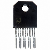
IC AMP AUDIO PWR 7.5W MONO 9SIL
Manufacturer
NXP Semiconductors
Type
Class ABr
Datasheet
1.TFA9841JN1112.pdf
(17 pages)
Specifications of TFA9841J/N1,112
Package / Case
9-SIL (Bent and Staggered Leads)
Output Type
1-Channel (Mono)
Max Output Power X Channels @ Load
7.5W x 1 @ 4 Ohm
Voltage - Supply
9 V ~ 26 V
Features
Depop, Mute, Short-Circuit and Thermal Protection, Standby
Mounting Type
Through Hole
Product
General Purpose Audio Amplifiers
Mounting Style
SMD/SMT
Lead Free Status / RoHS Status
Lead free / RoHS Compliant
Other names
568-3451-5
935274366112
TFA9841J
935274366112
TFA9841J


Philips Semiconductors
9397 750 12014
Preliminary data
8.2.1 Output power measurement
8.2.2 Headroom
8.2 Power amplifier
8.3 Mode selection
As shown in
the switch-on delay during charging of the input capacitors can be minimized. This
results in a good low frequency response and good switch-on behavior.
The power amplifier is a Single-Ended (SE) amplifier with an all-NPN output stage,
capable of delivering a peak output current of 3 A.
The output power as a function of the supply voltage is measured on the output pins
at THD = 10 %; see
The maximum output power is limited by the supply voltage of 26 V and the maximum
available output current is 3 A (repetitive peak current).
A minimum load of 4
Typical CD music requires at least 12 dB (factor 15.85) dynamic headroom,
compared to the average power output, for transferring the loudest parts without
distortion. At V
Average Listening Level (ALL) music power without any distortion yields:
The power dissipation can be derived from
12 dB, respectively (see
Table 4:
For the average listening level a power dissipation of 2.2 W can be used for a
heatsink calculation.
The TFA9841J has three functional modes, which can be selected by applying the
proper DC voltage to pin MODE (see
Table 5:
P
Headroom
0 dB
12 dB
V
0 to 0.8 V
4.5 V to (V
(V
o ALL
MODE
CC
2.0 V) to V
=
CC
5 10
---------------
Power rating as function of headroom
Mode selection
15.85
Equation
3.5 V)
CC
3
Power output (THD = 0.2 %)
P
P
CC
Rev. 01 — 06 February 2004
o
o(ALL)
= 18 V and P
=
= 5 W
Figure
315 mW
2, large capacitor values for the inputs are not necessary, so
= 315 mW
is required for V
Table
5.
4).
o
= 5 W (R
Table 5
CC
L
> 22 V; see
= 4 ) at THD = 0.2 % (see
Amplifier
standby
mute
on
Figure 9
and
Power dissipation
P
P
1-channel audio amplifier (1 x SE)
D
D
Figure
= 4.4 W
= 2.2 W
for a headroom of 0 dB and
© Koninklijke Philips Electronics N.V. 2004. All rights reserved.
Figure 6
3).
TFA9841J
Figure
7), the
4 of 17
(3)
Related parts for TFA9841J/N1,112
Image
Part Number
Description
Manufacturer
Datasheet
Request
R

Part Number:
Description:
Audio Amplifiers 1 X 7W SINGLE ENDED
Manufacturer:
NXP Semiconductors
Datasheet:

Part Number:
Description:
1-channel Audio Amplifier
Manufacturer:
NXP Semiconductors
Datasheet:
Part Number:
Description:
NXP Semiconductors designed the LPC2420/2460 microcontroller around a 16-bit/32-bitARM7TDMI-S CPU core with real-time debug interfaces that include both JTAG andembedded trace
Manufacturer:
NXP Semiconductors
Datasheet:

Part Number:
Description:
NXP Semiconductors designed the LPC2458 microcontroller around a 16-bit/32-bitARM7TDMI-S CPU core with real-time debug interfaces that include both JTAG andembedded trace
Manufacturer:
NXP Semiconductors
Datasheet:
Part Number:
Description:
NXP Semiconductors designed the LPC2468 microcontroller around a 16-bit/32-bitARM7TDMI-S CPU core with real-time debug interfaces that include both JTAG andembedded trace
Manufacturer:
NXP Semiconductors
Datasheet:
Part Number:
Description:
NXP Semiconductors designed the LPC2470 microcontroller, powered by theARM7TDMI-S core, to be a highly integrated microcontroller for a wide range ofapplications that require advanced communications and high quality graphic displays
Manufacturer:
NXP Semiconductors
Datasheet:
Part Number:
Description:
NXP Semiconductors designed the LPC2478 microcontroller, powered by theARM7TDMI-S core, to be a highly integrated microcontroller for a wide range ofapplications that require advanced communications and high quality graphic displays
Manufacturer:
NXP Semiconductors
Datasheet:
Part Number:
Description:
The Philips Semiconductors XA (eXtended Architecture) family of 16-bit single-chip microcontrollers is powerful enough to easily handle the requirements of high performance embedded applications, yet inexpensive enough to compete in the market for hi
Manufacturer:
NXP Semiconductors
Datasheet:
Part Number:
Description:
The XA-S3 device is a member of Philips Semiconductors? XA(eXtended Architecture) family of high performance 16-bitsingle-chip microcontrollers
Manufacturer:
NXP Semiconductors
Datasheet:

Part Number:
Description:
The NXP BlueStreak LH75401/LH75411 family consists of two low-cost 16/32-bit System-on-Chip (SoC) devices
Manufacturer:
NXP Semiconductors
Datasheet:
Part Number:
Description:
The NXP LPC3130/3131 combine an 180 MHz ARM926EJ-S CPU core, high-speed USB2
Manufacturer:
NXP Semiconductors
Datasheet:
Part Number:
Description:
The NXP LPC3141 combine a 270 MHz ARM926EJ-S CPU core, High-speed USB 2
Manufacturer:
NXP Semiconductors
Part Number:
Description:
The NXP LPC3143 combine a 270 MHz ARM926EJ-S CPU core, High-speed USB 2
Manufacturer:
NXP Semiconductors

Part Number:
Description:
The NXP LPC3152 combines an 180 MHz ARM926EJ-S CPU core, High-speed USB 2
Manufacturer:
NXP Semiconductors