TDA7264A STMicroelectronics, TDA7264A Datasheet
TDA7264A
Specifications of TDA7264A


Related parts for TDA7264A


TDA7264A Summary of contents
Page 1
stereo amplifier with mute and standby Features Wide supply voltage range (up to ±22.5 V) Split supply High output power – into 8 Ω with V = ±20 V and ...
Page 2
Pin description 1 Pin description Figure 2. Pin connection (top view) 2/ Tab connected to pin 5 Doc ID 1477 Rev 6 TDA7264 IN (1) GND IN ( MUTE/ST-BY OUTPUT ...
Page 3
TDA7264 2 Electrical specifications 2.1 Absolute maximum ratings Table 2. Absolute maximum ratings Symbol V DC supply voltage S I Output Peak Current (internally limited power Dissipation T tot T Operating temperature op T Junction temperature j T ...
Page 4
Electrical specifications Table 4. Electrical specifications (continued) Symbol THD Total harmonic distortion C Crosstalk T SR Slew rate G Closed-loop voltage gain V ∆G Voltage gain matching V eN Total input noise R Input resistance i SVRR Supply voltage rejection ...
Page 5
TDA7264 3 Characterization curves Figure 3. Quiescent current vs Supply Voltage Figure 4. Frequency response Doc ID 1477 Rev 6 Characterization curves 5/14 ...
Page 6
Characterization curves Figure 5. Output power vs supply voltage Figure 6. Distortion vs output power Figure 7. Crosstalk vs frequency 6/14 Doc ID 1477 Rev 6 TDA7264 ...
Page 7
TDA7264 Figure 8. SVRR vs frequency Figure 9. Attenuation and quiescent current vs voltage on pin 4 Figure 10. Power dissipation vs output power Doc ID 1477 Rev 6 Characterization curves 7/14 ...
Page 8
Mute and standby modes 4 Mute and standby modes Pin 4 (MUTE/STANDBY) controls the amplifier status by two different thresholds referenced given in S Table 5. Mute and standby thresholds on pin 5 Nominal voltage on pin ...
Page 9
TDA7264 5 Applications information Figure 12. Schematic of demo board SW1 ST-BY DZ SW1 SW2 A A Standby A B Standby B B Mute B A Play Figure 13. Component layout of demo-board R2 C3 15K 1µF ...
Page 10
Applications information Table 6. Recommended component values for demo board Recommended Component R1 10 kΩ kΩ kΩ kΩ 4.7 Ω R5 µF C1 µF 1000 µF C4, C6 0.1 ...
Page 11
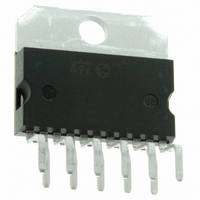
TDA7264 6 Package mechanical data The TDA7264 comes in a 8-pin Multiwatt package with pin 5 internally connected to the metal tab. Figure 14. Multiwatt8 outline drawing In order to meet environmental requirements, ST offers these devices in different grades ...
Page 12
Package mechanical data Table 7. Multiwatt8 package dimensions Reference Diam.1 Diam.2 12/14 Dimensions in mm Min ...
Page 13
... TDA7264 7 Revision history Table 8. Document revision history Date Jan-2004 01-Jul-2009 Revision 5 First issue in EDOCS 6 Removed references to TDA7264A Doc ID 1477 Rev 6 Revision history Changes 13/14 ...
Page 14
... Information in this document is provided solely in connection with ST products. STMicroelectronics NV and its subsidiaries (“ST”) reserve the right to make changes, corrections, modifications or improvements, to this document, and the products and services described herein at any time, without notice. All ST products are sold pursuant to ST’s terms and conditions of sale. ...