TDA7295S STMicroelectronics, TDA7295S Datasheet
TDA7295S
Specifications of TDA7295S
Available stocks


Related parts for TDA7295S


TDA7295S Summary of contents
Page 1
... MODULARITY (MORE DEVICES CAN BE EASILY CONNECTED IN PARALLEL TO DRIVE VERY LOW IMPEDANCES) DESCRIPTION The TDA7295S is a monolithic integrated circuit in Multiwatt15 package, intended for use as audio class AB amplifier in Hi-Fi field applications (Home Stereo, self powered loudspeakers, Top- Figure 1: Typical Application and Test Circuit ...
Page 2
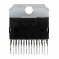
... TDA7295S PIN CONNECTION (Top view) TAB CONNECTED TO PIN 8 QUICK REFERENCE DATA Symbol Parameter V Supply Voltage Operating S G Closed Loop Gain LOOP Output Power P tot SVR Supply Voltage Rejection ABSOLUTE MAXIMUM RATINGS Symbol V Supply Voltage (No Signal GND Voltage Referred to -V STAND- Input Voltage (inverting) Referred to -V ...
Page 3
... 26V 22V 10 34V L S (***) 27V 5W 1kHz 0.1 to 30W 20Hz to 20kHz 22V 5W 1kHz 0.1 to 30W 20Hz to 20kHz curve f = 20Hz to 20kHz 100Hz 0.5Vrms ripple or GND) TDA7295S = 30V 30dB Min. Typ. Max 500 0.005 0.1 0.01 0 20Hz to 20kHz 100 60 75 150 1.5 3 1.5 3.5 ...
Page 4
... TDA7295S Figure 2: Typical Application P.C. Board and Component Layout (scale 1:1) 4/13 ...
Page 5
... GND, a Boucherot Cell, in order to avoid dangerous spurious oscillations when the speakers terminal are shorted. The suggested Boucherot Resistor is 3.9 /2W and the capacitor D98AU821 TDA7295S LARGER THAN SMALLER THAN SUGGESTED SUGGESTED INCREASE INPUT DECREASE INPUT ...
Page 6
... The solution shown as a principle shematic by Fig3 represents the DMOS unity - gain output buffer of the TDA7295S. This large-signal, high-power buffer must be ca- pable of handling extremely high current and volt- age levels while maintaining acceptably low har- monic distortion and good behaviour over Figure 3: Principle Schematic of a DMOS unity-gain buffer ...
Page 7
... These are both due to the low effi- D93AU014 ciency of conventional AB class amplifier ap- proaches. Here below (figure 6) is described a circuit pro- posal for a high efficiency amplifier which can be adopted for both HI-FI and CAR-RADIO applica- tions. TDA7295S ST-BY OFF D98AU817 7/13 ...
Page 8
... The current generators formed by T4, T7, zener diodes Z1, Z2 and resistors R7,R8 define the minimum drop across the power MOS transistors of the TDA7295S. L1, L2, L3 and the snubbers C9, R1 and C10, R2 stabilize the loops formed by the "bootstrap" circuits and the output stage of the TDA7295S ...
Page 9
... C12 330nF 330nF R12 13K PLAY C13 R13 20K ST-BY R2 R14 30K R15 10K 1N4148 8 C10 10 330nF C14 BYW98100 D7 1N4001 TDA7295S T3 BC394 270 270 BDX53A T4 BC393 BC393 R17 270 1N4148 R6 20K Z1 3.9V 13 C11 680 2 R7 3.3K R16 13K 14 R18 270 6 C15 ...
Page 10
... TDA7295S Figure 6b: PCB - Solder Side of the fig. 6. Figure 7: Modular Application Circuit MASTER 680 C1 470nF R1 22K VMUTE R5 10K VSTBY R4 22K SLAVE 10/13 C7 100nF R3 22K BUFFER +Vs DRIVER SGND 4 MUTE 10 MUTE THERMAL STBY 9 SHUTDOWN STBY 1 8 STBY-GND - 100nF -Vs C7 100nF BUFFER +Vs DRIVER ...
Page 11
... Figure 8a: Modular Application P.C. Board and Component Layout (scale 1:1) (Component SIDE) Figure 8b: Modular Application P.C. Board and Component Layout (scale 1:1) (Solder SIDE) TDA7295S 11/13 ...
Page 12
... TDA7295S mm DIM. MIN. TYP. MAX. MIN 2. 0.49 0.55 0.019 F 0.66 0.75 0.026 G 1.02 1.27 1.52 0.040 G1 17.53 17.78 18.03 0.690 H1 19.6 0.772 H2 20.2 L 21.9 22.2 22.5 0.862 L1 21.7 22.1 22.5 0.854 L2 17.65 18.1 0.695 L3 17.25 17.5 17.75 0.679 L4 10.3 10 ...
Page 13
... STMicroelectronics – Printed in Italy – All Rights Reserved Australia - Brazil - Canada - China - Finland - France - Germany - Hong Kong - India - Israel - Italy - Japan - Malaysia - Malta - Morocco - Singapore - Spain - Sweden - Switzerland - United Kingdom - United States. The ST logo is a registered trademark of STMicroelectronics STMicroelectronics GROUP OF COMPANIES http://www.st.com TDA7295S 13/13 ...