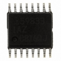
ISL59833IAZ Intersil, ISL59833IAZ Datasheet

ISL59833IAZ
Specifications of ISL59833IAZ
Available stocks
Related parts for ISL59833IAZ
ISL59833IAZ Summary of contents
Page 1
... MARKING REEL ISL59833IAZ 59833 IAZ - 16 Ld QSOP MDP0040 ISL59833IAZ-T7 59833 IAZ 7” QSOP MDP0040 NOTE: Intersil Pb-free plus anneal products employ special Pb-free material sets; molding compounds/die attach materials and 100% matte tin plate termination finish, which are RoHS compliant and compatible with both SnPb and Pb-free soldering operations ...
Page 2
... Power Supply Rejection Ratio 2 ISL59833 Thermal Information Operating Temperature . . . . . . . . . . . . . . . . . . . . . . .-40°C to +85°C Maximum Die Temperature . . . . . . . . . . . . . . . . . . . . . . . . . . +150°C Storage Temperature . . . . . . . . . . . . . . . . . . . . . . . .-65°C to +150°C Lead Temperature . . . . . . . . . . . . . . . . . . . . . . . . . . . . . . . . . +260°C Power Dissipation . . . . . . . . . . . . . . . . . . . . . . . . . . . . . See Curves Pb-free reflow profile . . . . . . . . . . . . . . . . . . . . . . . . . .see link below http://www.intersil.com/pbfree/Pb-FreeReflow.asp = +3.3V, REF = GND +25 CC ...
Page 3
DC Electrical Specifications V PARAMETER DESCRIPTION I Supply Current S Pin Descriptions PIN NUMBER PIN NAME 1 RIN 2 GIN 3 BIN 4 REF 5 VEE 6 GND 7 VEE OUT 8 DGND 9 DVCC 10 NC 11, 13 VCC ...
Page 4
Pin Descriptions (Continued) PIN NUMBER PIN NAME BOUT 15 GOUT 16 ROUT Typical Performance Curves 0pF 1kΩ 150Ω 75Ω 10M FREQUENCY (Hz) ...
Page 5
Typical Performance Curves 1.6 1.2 0.8 0.4 0 2.2 2.4 2.6 2.8 3.0 3.2 SUPPLY VOLTAGE (V) FIGURE 5. PEAKING vs SUPPLY VOLTAGE - 500Ω -30 L -40 -50 -60 -70 -80 -90 -100 ...
Page 6
Typical Performance Curves 100 10 1 0.1 0.01 10k 100k 1M FREQUENCY (Hz) FIGURE 11. OUTPUT IMPEDANCE vs FREQUENCY 1k 100 10 1 0.1 10 100 1k 10k FREQUENCY (Hz) FIGURE 13. VOLTAGE AND CURRENT NOISE vs FREQUENCY -30 -40 ...
Page 7
Typical Performance Curves 0 -0.02 -0.04 -0.06 -0.08 IRE FIGURE 17. DIFFERENTIAL PHASE TIME (200ns/DIV) FIGURE 19. ENABLE TIME TIME (10ns/DIV) FIGURE 21. LARGE SIGNAL RISE AND FALL TIMES 7 ISL59833 (Continued) FIGURE 20. SMALL SIGNAL RISE AND FALL TIMES ...
Page 8
Typical Performance Curves 3.25 3.00 2.75 2.50 50 250 450 650 LOAD RESISTANCE (Ω) FIGURE 23. MAXIMUM OUTPUT MAGNITUDE vs LOAD RESISTANCE JEDEC JESD51-3 LOW EFFECTIVE THERMAL CONDUCTIVITY TEST BOARD 1.4 1.2 1.0 791mW 0.8 0.6 0.4 0 ...
Page 9
Block Diagram 9 ISL59833 6dB - REF 6dB - 6dB - CHARGE PUMP OUT IN REFERENCE CC R OUT G OUT B OUT ...
Page 10
ISL59833 + DC-Restore Solution 2kΩ 2kΩ 75Ω 75Ω 0.1µF 0.1µ 0.1µF 0.1µF 5 75Ω 75Ω C 0.1µF 0.1µF 6 ...
Page 11
Demo Board Schematic RED_IN R 1 75Ω GREEN_IN R 2 75Ω 75Ω 499Ω 1kΩ OFFSET CONTROL Description of Operation and Application Information Theory Of Operation The ISL59833 is a highly practical and ...
Page 12
Figure 11). THE CHARGE PUMP The ISL59833 charge pump provides a ...
Page 13
THE VREF PIN Applying a voltage to the VREF pin simply places that voltage on what would usually be the ground side of the gain resistor of the amplifier, resulting in a DC-level shift of the output signal. Applying 100mV ...
Page 14
This limit is set by the design of the internal metal interconnections. POWER DISSIPATION With the high output ...
Page 15
... Accordingly, the reader is cautioned to verify that data sheets are current before placing orders. Information furnished by Intersil is believed to be accurate and reliable. However, no responsibility is assumed by Intersil or its subsidiaries for its use; nor for any infringements of patents or other rights of third parties which may result from its use ...


