HFA1105IBZ Intersil, HFA1105IBZ Datasheet
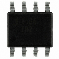
IC OPAMP CFA 330MHZ LP 8-SOIC

HFA1105IBZ

Manufacturer Part Number
HFA1105IBZ
Description
IC OPAMP CFA 330MHZ LP 8-SOIC
Manufacturer
Intersil
Datasheet

Specifications of HFA1105IBZ

Applications
Current Feedback
Number Of Circuits
1
-3db Bandwidth
330MHz
Slew Rate
1000 V/µs
Current - Supply
5.8mA
Current - Output / Channel
60mA
Voltage - Supply, Single/dual (±)
±4.5 V ~ 5.5 V
Mounting Type
Surface Mount
Package / Case
8-SOIC (0.154", 3.90mm Width)
Supply Voltage Range
± 4.5V To ± 5.5V
No. Of Amplifiers
1
Output Current
60mA
Amplifier Output
Single Ended
Operating Temperature Range
-40°C To +85°C
Amplifier Case Style
SOIC
Rohs Compliant
Yes
Lead Free Status / RoHS Status
Lead free / RoHS Compliant

Available stocks

Company
Part Number
Manufacturer
Quantity
Price
Part Number:
HFA1105IBZ
Manufacturer:
INTERSIL
Quantity:
20 000
330MHz, Low Power, Current Feedback
Video Operational Amplifier
The HFA1105 is a high speed, low power current feedback
amplifier built with Intersil’s proprietary complementary
bipolar UHF-1 process.
This amplifier features an excellent combination of low
power dissipation (58mW) and high performance. The slew
rate, bandwidth, and low output impedance (0.08Ω) make
this amplifier a good choice for driving Flash ADCs.
Component and composite video systems also benefit from
this op amp’s excellent gain flatness, and good differential
gain and phase specifications. The HFA1105 is ideal for
interfacing to Intersil’s line of video crosspoint switches
(HA4201, HA4600, HA4314, HA4404, HA4344), to create
high performance, low power switchers and routers.
The HFA1105 is a low power, high performance upgrade for
the CLC406. For a comparable amplifier with output disable
or output limiting functions, please see the data sheets for
the HFA1145 and HFA1135 respectively.
For Military grade product, please refer to the HFA1145/883
data sheet.
Ordering Information
NOTES:
HFA1105IB
HFA1105IB96
HFA1105IBZ
(Note 1)
HFA1105IBZ96
(Note 1)
HFA11XXEVAL
(Note 2)
1. Intersil Pb-free plus anneal products employ special Pb-free
2. Requires a SOIC-to-DIP adapter. See “Evaluation Board” section
NUMBER
material sets; molding compounds/die attach materials and
100% matte tin plate termination finish, which are RoHS
compliant and compatible with both SnPb and Pb-free soldering
operations. Intersil Pb-free products are MSL classified at
Pb-free peak reflow temperatures that meet or exceed the
Pb-free requirements of IPC/JEDEC J STD-020.
inside.
PART
1105IB
1105IB
1105IBZ
1105IBZ
DIP Evaluation Board for High Speed
Op Amps
MARKING
PART
8 Ld SOIC Tape and Reel
8 Ld SOIC Tape and Reel (Pb-free)
®
RANGE (°C) PACKAGE
-40 to 85
-40 to 85
TEMP.
1
Data Sheet
8 Ld SOIC
8 Ld SOIC
(Pb-free)
M8.15
M8.15
DWG. #
PKG.
1-888-INTERSIL or 1-888-468-3774
CAUTION: These devices are sensitive to electrostatic discharge; follow proper IC Handling Procedures.
Features
• Low Supply Current . . . . . . . . . . . . . . . . . . . . . . . . 5.8mA
• High Input Impedance . . . . . . . . . . . . . . . . . . . . . . . 1MΩ
• Wide -3dB Bandwidth. . . . . . . . . . . . . . . . . . . . . . 330MHz
• Very Fast Slew Rate. . . . . . . . . . . . . . . . . . . . . . 1000V/µs
• Gain Flatness (to 75MHz) . . . . . . . . . . . . . . . . . . . ±0.1dB
• Differential Gain . . . . . . . . . . . . . . . . . . . . . . . . . . . 0.02%
• Differential Phase . . . . . . . . . . . . . . . . . . . . . . . . . . . 0.03°
• Pin Compatible Upgrade for CLC406
• Pb-Free Plus Anneal Available (RoHS Compliant)
Applications
• Flash A/D Drivers
• Video Switching and Routing
• Professional Video Processing
• Video Digitizing Boards/Systems
• Multimedia Systems
• RGB Preamps
• Medical Imaging
• Hand Held and Miniaturized RF Equipment
• Battery Powered Communications
Pinout
All other trademarks mentioned are the property of their respective owners.
June 6, 2006
|
Intersil (and design) is a registered trademark of Intersil Americas Inc.
Copyright © Intersil Americas Inc. 2003, 2006. All Rights Reserved
+IN
NC
-IN
V-
1
2
3
4
HFA1105 (SOIC)
TOP VIEW
+
-
8
7
6
5
NC
V+
OUT
NC
HFA1105
FN3395.8

Related parts for HFA1105IBZ

HFA1105IBZ Summary of contents

Page 1

... HFA1105IB 1105IB - HFA1105IB96 1105IB 8 Ld SOIC Tape and Reel HFA1105IBZ 1105IBZ - (Note 1) HFA1105IBZ96 1105IBZ 8 Ld SOIC Tape and Reel (Pb-free) (Note 1) HFA11XXEVAL DIP Evaluation Board for High Speed (Note 2) Op Amps NOTES: 1. Intersil Pb-free plus anneal products employ special Pb-free material sets; molding compounds/die attach materials and ...

Page 2

Absolute Maximum Ratings Supply Voltage (V+ to V-). . . . . . . . . . . . . . . . . . . . . . . . . . . . . . 11V DC Input ...

Page 3

Electrical Specifications V SUPPLY PARAMETER Inverting Input Resistance Input Capacitance Input Voltage Common Mode Range (Implied by V CMRR and - BIAS Input Noise Voltage Density (Note 8) Non-Inverting Input Noise Current Density (Note 8) Inverting ...

Page 4

Electrical Specifications V SUPPLY PARAMETER TRANSIENT CHARACTERISTICS Rise and Fall Times Overshoot (Note 0.5V 1ns) OUT IN RISE Overshoot (Note 0. ...

Page 5

Application Information Optimum Feedback Resistor Although a current feedback amplifier’s bandwidth dependency on closed loop gain isn’t as severe as that of a voltage feedback amplifier, there can be an appreciable decrease in bandwidth at higher gains. This decrease may ...

Page 6

100 200 50 150 250 LOAD CAPACITANCE (pF) FIGURE 1. RECOMMENDED SERIES OUTPUT RESISTOR vs LOAD CAPACITANCE Evaluation Board The performance of the HFA1105 may ...

Page 7

Typical Performance Curves 200 510Ω S 150 100 50 0 -50 -100 -150 -200 TIME (5ns/DIV) FIGURE 3. SMALL SIGNAL PULSE RESPONSE 2 510Ω S 1.5 1.0 0.5 ...

Page 8

Typical Performance Curves 200 180Ω 150 F 100 50 0 -50 -100 -150 -200 TIME (5ns/DIV) FIGURE 9. SMALL SIGNAL PULSE RESPONSE 2 + 180Ω 1.5 F 1.0 0.5 ...

Page 9

Typical Performance Curves (+1) OUT P (-1, +2) OUT P 510Ω (+ FREQUENCY (MHz) FIGURE 15. FULL POWER BANDWIDTH 500 400 A ...

Page 10

Typical Performance Curves 0.8 0.6 0.4 0.2 0.1 0 -0.2 -0.4 -0.6 -0 TIME (ns) FIGURE 21. SETTLING RESPONSE - -40 -50 -60 - OUTPUT POWER (dBm) FIGURE ...

Page 11

Die Characteristics DIE DIMENSIONS: 59 mils x 59 mils x 19 mils 1500µm x 1500µm x 483µm METALLIZATION: Type: Metal 1: AICu(2%)/TiW ±0.4k Å Å Thickness: Metal 1: 8k Type: Metal 2: AICu(2%) ±0.8k Å Å Thickness: Metal 2: 16k ...

Page 12

... Accordingly, the reader is cautioned to verify that data sheets are current before placing orders. Information furnished by Intersil is believed to be accurate and reliable. However, no responsibility is assumed by Intersil or its subsidiaries for its use; nor for any infringements of patents or other rights of third parties which may result from its use ...

Related keywords