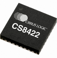
CS8422-CNZ Cirrus Logic Inc, CS8422-CNZ Datasheet - Page 32

CS8422-CNZ
Manufacturer Part Number
CS8422-CNZ
Description
IC SAMPLE RATE CONVERTER 32QFN
Manufacturer
Cirrus Logic Inc
Type
Sample Rate Converterr
Datasheet
1.CS8422-CNZ.pdf
(82 pages)
Specifications of CS8422-CNZ
Package / Case
32-QFN
Applications
Digital Audio
Mounting Type
Surface Mount
Maximum Operating Temperature
+ 125 C
Minimum Operating Temperature
- 55 C
Mounting Style
SMD/SMT
Package
32QFN
Operating Temperature
-55 to 125 °C
Audio Control Type
Sample Rate Converter
Control Interface
I2C, SPI
Supply Voltage Range
1.71V To 5.25V
Operating Temperature Range
-40°C To +85°C
Audio Ic Case Style
QFN
No. Of Pins
32
Rohs Compliant
Yes
Lead Free Status / RoHS Status
Lead free / RoHS Compliant
For Use With
598-1568 - BOARD EVAL FOR CS8422 RCVR
Lead Free Status / Rohs Status
Lead free / RoHS Compliant
Other names
598-1732
Available stocks
Company
Part Number
Manufacturer
Quantity
Price
Company:
Part Number:
CS8422-CNZ
Manufacturer:
CIRRUS
Quantity:
99
Part Number:
CS8422-CNZ
Manufacturer:
CIRRUS
Quantity:
20 000
Part Number:
CS8422-CNZR
Manufacturer:
CIRRUS
Quantity:
20 000
32
6.4.1
6.4.2
6.5
6.6
6.6.1
frequencies will be derived from the XTI-XTO clock when clock switching has taken place and the RMCK-
to-LRCK ratio will be maintained.
When clock switching is not enabled and the PLL has lost lock, RMCK will be derived from the VCO idle
frequency. The frequency of the RMCK output will still be determined by the ratio selected by the RMCK[2:0]
bits in register 09h, or the MS_SEL pin in Hardware Mode. When the PLL has lost lock, the VCO idle fre-
quency is equivalent to AES3 input data with Fs 54 kHz ± 5% (or ISCLK 3.456 MHz ± 5%).
AES11 Behavior
When an AES3-derived OLRCK is configured as a master, the rising or falling edge of OLRCK (depending
on the serial port interface format setting) will be within -1.5%(1/Fs) to 1.5%(1/Fs) from the start of the pre-
amble X/Z. In master mode, the latency through the receiver depends on the input sample frequency. In
master mode the latency of the audio data will be 3 frames in AES3 direct mode, and 4 frames in all other
cases.
When an AES3-derived OLRCK is configured as a slave, any synchronized input within +/-25% of an AES3
frame from the positive or negative edge of OLRCK (depending on the serial port interface format setting)
will be treated as being sampled at the same time. Since the CS8422 has no control of the OLRCK in slave
mode, the latency of the data through the part will be a multiple of 1/Fs plus the intrinsic delay between OL-
RCK and the preambles also present in master mode.
Both of these conditions are within the tolerance range set forth in the AES11 standard.
Error and Status Reporting
While decoding the incoming bi-phase encoded data stream, the CS8422 has the ability to identify various
error conditions. Refer to
Hardware Mode Control
In Hardware Mode, XTI System Clock Mode is always enabled.
Software Mode Control
In Software Mode, XTI System Clock Mode is controlled through the register described in
“Clock Control (02h)” on page
Software Mode
Software Mode allows the most flexibility in reading errors. When unmasked, bits in the Receiver Error
register (0Ch) indicate the following errors:
1. QCRC – CRC error in Q subcode data.
2. CCRC – CRC error in channel status data.
3. UNLOCK – PLL is not locked to incoming bi-phase data stream, or 2 valid Z preambles have not yet
4. V – Data Validity bit is set.
5. CONF – The input data stream may be near error condition due to jitter degradation.
6. BIP – Bi-phase encoding error.
7. PAR – Parity error in incoming data.
been detected.
Sections 6.6.1
47.
and
6.6.2
for details.
Section 11.2
CS8422
DS692F1


