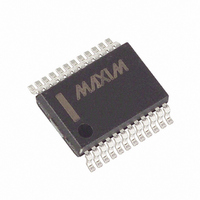
MAX5440EAG+ Maxim Integrated Products, MAX5440EAG+ Datasheet - Page 12

MAX5440EAG+
Manufacturer Part Number
MAX5440EAG+
Description
IC CNTRL VOL STEREO 24-SSOP
Manufacturer
Maxim Integrated Products
Type
Stereo Audio Volume Controlr
Datasheet
1.MAX5440EAGT.pdf
(16 pages)
Specifications of MAX5440EAG+
Applications
Automotive Systems, Desktop Audio, Set-Top Boxes
Mounting Type
Surface Mount
Package / Case
24-SSOP
Number Of Pots
Dual
Taps Per Pot
32
Resistance
1 Ohms
Wiper Memory
Volatile
Digital Interface
Serial
Operating Supply Voltage
2.7 V to 5.5 V
Supply Current
1.4 uA
Maximum Operating Temperature
+ 85 C
Minimum Operating Temperature
- 40 C
Description/function
Stereo Volume Control with Rotary Encoder Interface
Mounting Style
SMD/SMT
Supply Voltage (max)
5.5 V
Supply Voltage (min)
2.7 V
Temperature Coefficient
35 PPM / C
Tolerance
30 %
Lead Free Status / RoHS Status
Lead free / RoHS Compliant
The power-on comparators monitor (V
(V
either of the supplies is brought back to the normal
operating voltage. The power-on reset feature sets both
wipers to -12dB. The wipers initially wake up in mute
mode (-90dB) and move to the -12dB position when V
= V
With DC inputs at V
exceeding the timeout period. A power-on reset places
the MAX5440 in volume-control mode.
Upon entering shutdown, the MAX5440 stores the last
wiper settings. The wipers move to the L_ end of the
resistor string. The wipers move to the L_ end of the
resistor string when V
during shutdown. With DC inputs at V
wipers move after exceeding the timeout period. Exiting
shutdown restores the wipers to their previous settings.
The MAX5440 features a mute function input, MUTE.
Successive low pulses on MUTE toggle its setting.
Activating the mute function forces both wipers to maxi-
mum attenuation (-90dB typ). Deactivating the mute
function returns the wipers to their previous settings.
Rotating the encoder clockwise (increasing gray code
count) also deactivates mute, setting the wipers to their
previous positions. MUTE is internally pulled high with a
45kΩ resistor to V
tap 31 position (-62dB attenuation) further commands
to lower the volume (decreasing gray code count)
place the wipers in the mute position (see
Rotating the encoder to a lower attenuation or a pulse
to MUTE returns the wipers to tap 31.
Table 2. LED Settings in Volume Mode
Stereo Volume Control
with Rotary Encoder Interface
12
LOGIC
VOLUME POSITION (dB)
L
______________________________________________________________________________________
to eliminate clicks and pops during power-up.
-54 to mute (-90)
- GND). A power-on reset is initiated when
-10 to -18
-20 to -28
-30 to -38
-40 to -52
0 to -8
LOGIC
H
H
= V
and V
. When both wipers are in the
L
Mute Function ( MUTE )
to eliminate clicks and pops
L
, the wipers move after
Shutdown ( SHDN )
Power-On Reset
LED0
1
1
1
1
1
0
DD
H
and V
- V
Table
SS
L
) and
, the
1).
LED1
H
VOLUME LED OUTPUTS (1 = LED IS ON)
1
1
1
1
0
0
The open-drain MODEIND indicates volume-control
mode or balance-control mode for the MAX5440.
Connect MODEIND to an LED with a series resistor to
V
control mode. When the LED is off, the MAX5440 is in
volume-control mode. See the Mode Control (MODE)
section for more detail on switching between modes.
The MAX5440 includes five indicator LED drivers to dis-
play the current wiper settings in either volume or bal-
ance mode. Connect the LEDIND_ outputs to the LEDs
and to V
typical application circuits.
In volume-control mode, all LEDs are off when the
wipers reach the highest attenuation levels (mute). All
LEDs are on at the lowest attenuation levels (0dB).
Table 2 shows the LED display as the wipers transition
through various attenuation levels.
In balance-control mode, only one LED is on at a time
to indicate the current balance setting. Figure 5 shows
the LEDs display for the current balance setting. When
LED2 is on, the display indicates that the channels are
centered or balanced at a set volume level. Turning the
encoder clockwise (an increasing gray code count)
turns LED3 on to represent a balance shift towards
channel 1. When LED4 turns on, the balance shifts
completely toward channel 1 and channel 0 is fully
attenuated. From a balanced position, turning the
encoder counterclockwise (a decreasing gray code
count) turns on LED1, and then LED0 to indicate a bal-
ance shift towards channel 0.
LOGIC
. When the LED is on, the MAX5440 is in balance-
LOGIC
LED2
1
1
1
0
0
0
through a series resistor as shown in the
Mode Indicator ( MODEIND )
LED3
Level Indicator LEDs
1
1
0
0
0
0
LED4
1
0
0
0
0
0


