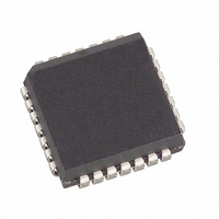
DS2167Q Maxim Integrated Products, DS2167Q Datasheet - Page 6

DS2167Q
Manufacturer Part Number
DS2167Q
Description
IC PROC ADPCM 16/24/32K 28-PLCC
Manufacturer
Maxim Integrated Products
Type
ADPCM Processorr
Datasheet
1.DS2167.pdf
(15 pages)
Specifications of DS2167Q
Mounting Type
Surface Mount
Package / Case
28-LCC, 28-PLCC
Lead Free Status / RoHS Status
Contains lead / RoHS non-compliant
Applications
-
Available stocks
Company
Part Number
Manufacturer
Quantity
Price
Company:
Part Number:
DS2167QN/T&R
Manufacturer:
Maxim Integrated
Quantity:
10 000
both X and Y interfaces, the device enters a low-power
standby mode. The DS2167 will power-up within
200 ms after the X or Y side is reactivated (IPD=0) from
standby. The DS2168 requires an external hardware re-
set after IPD is cleared to “wake-up” from standby. The
DS2168 will power-up immediately after the low-high
transition on RST.
ALRST resets the algorithm coefficients for the selected
channel to their initial values. ALRST will be cleared by
the device when the algorithm reset is complete.
The bypass feature is enabled when BYP is set and IPD
is clear. During bypass, no expansion or compression of
data occurs. This feature allows the user to interchange
timeslots under control of the timeslot registers. Bypass
ADDRESS/COMMAND BYTE Figure 3
DS2167/DS2168
022698 6/15
(MSB)
SYMBOL
–
X/Y
A5
A4
A3
A2
A1
A0
–
X/Y
POSITION
ACB.7
ACB.6
ACB.5
ACB.4
ACB.3
ACB.2
ACB.1
ACB.0
A5
NAME AND DESCRIPTION
Reserved, must be 0 for proper operation.
X/Y Channel Select.
0 = Update channel Y characteristics.
1 = Update channel X characteristics.
MSB of Device Address.
LSB of Device Address.
A4
operates on byte-wide slots when CP/EX=1, on nibble-
wide slots when CP/EX=0.
A-law (µ/A=0) or µ-law PCM (µ/A=1) coding is indepen-
dently selected for the X and Y side interfaces by bit µ/A.
If BYP and IPD are clear, CP/EX determines if input data
is to be compressed or expanded.
TIMESLOT ASSIGNMENT
On-chip counters establish when PCM data I/O occurs
and are programmed via the timeslot registers. Timeslot
size (4 or 8 bits wide) is determined by the state of
CP/EX. Timeslots are counted from the rising edge of
FSX and FSY.
A3
A2
A1
(LSB)
a0


