ADCMP341YRJZ-REEL7 Analog Devices Inc, ADCMP341YRJZ-REEL7 Datasheet
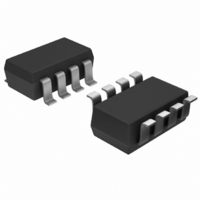
IC COMPARATOR DUAL OD SOT23-8

ADCMP341YRJZ-REEL7

Manufacturer Part Number
ADCMP341YRJZ-REEL7
Description
IC COMPARATOR DUAL OD SOT23-8
Manufacturer
Analog Devices Inc
Type
with Voltage Referencer
Datasheet

Specifications of ADCMP341YRJZ-REEL7

Number Of Elements
2
Output Type
Open Drain
Voltage - Supply
1.7 V ~ 5.5 V
Mounting Type
Surface Mount
Package / Case
SOT-23-8
Comparator Type
General Purpose
No. Of Comparators
2
Response Time
8µs
Ic Output Type
Open Drain
Supply Current
6.5µA
Supply Voltage Range
1.7V To 5.5V
Amplifier Case Style
SOT-23
Rohs Compliant
Yes
Lead Free Status / RoHS Status
Lead free / RoHS Compliant
Other names
ADCMP341YRJZ-REEL7TR

Available stocks

Company
Part Number
Manufacturer
Quantity
Price
Part Number:
ADCMP341YRJZ-REEL7
Manufacturer:
TOSHIBA
Quantity:
1 001
Part Number:
ADCMP341YRJZ-REEL7
Manufacturer:
ADI/亚德诺
Quantity:
20 000
FEATURES
400 mV ± 0.275% threshold
User programmable hysteresis via resistor string
Supply range: 1.7 V to 5.5 V
Low quiescent current: 6.5 μA typical
Input range includes ground
Low input bias current: ±5 nA maximum
Open-drain outputs
Supports wired-AND connections
Input polarities:
Small SOT-23 package
APPLICATIONS
Portable applications
Li-Ion monitoring
Handheld instruments
LED/relay driving
Optoisolator driving
Control systems
GENERAL DESCRIPTION
The ADCMP341/ADCMP343 consist of two low power, high
accuracy comparators with a 400 mV reference in an 8-lead
SOT-23 package. Operating within a supply range of 1.7 V to
5.5 V, the devices only draw 6.5 μA (typical), making them ideal
for low voltage system monitoring and portable applications.
Hysteresis is determined using three resistors in a string configura-
tion with the upper and lower tap points connected to the
±INA_U and ±INA_L pins of each comparator, respectively.
The state of the outputs of the comparators selects which pin is
internally connected to the comparators input. Therefore, a
change of state in the comparators output results in one of the
inputs being switched in to the comparator and the other being
switched out. This provides the user with a fully flexible and
accurate method of setting the hysteresis. One input of each
comparator is internally connected to the reference. The other
input is available externally, via an internal mux, through pins
±INA_U or ±INA_L. The state of the output determines which
of these pins is connected at any one time.
The comparator outputs are open-drain with the output stage
sinking capability guaranteed greater than 5 mA over temperature.
The ADCMP341 has noninverting inputs and the ADCMP343
has inverting inputs. The devices are suitable for portable,
commercial, industrial, and automotive applications.
Rev. 0
Information furnished by Analog Devices is believed to be accurate and reliable. However, no
responsibility is assumed by Analog Devices for its use, nor for any infringements of patents or other
rights of third parties that may result from its use. Specifications subject to change without notice. No
license is granted by implication or otherwise under any patent or patent rights of Analog Devices.
Trademarks and registered trademarks are the property of their respective owners.
ADCMP341 noninverting
ADCMP343 inverting
Dual 0.275% Comparators and Reference
with Programmable Hysteresis
One Technology Way, P.O. Box 9106, Norwood, MA 02062-9106, U.S.A.
Tel: 781.329.4700
Fax: 781.461.3113
Figure 3. Hysteresis programmed to 513 mV @ V
1
2
CH1
OUTA
V
FUNCTIONAL BLOCK DIAGRAMS
VINA
VINB
VINA
VINB
IN
2.00V
R1
R2
R3
R1
R2
R3
ADCMP341/ADCMP343
+INA_U
+INB_U
+INA_L
+INB_L
–INA_U
–INB_U
–INA_L
–INB_L
CH2 500mV
©2007 Analog Devices, Inc. All rights reserved.
Figure 1. ADCMP341
Figure 2. ADCMP343
ADCMP341
ADCMP343
GND
GND
V
V
M100ms
DD
DD
400mV
400mV
OUTA
OUTB
OUTA
OUTB
IN
R1 = 22kΩ
R2 = 2.2kΩ
R3 = 6.2kΩ
on ADCMP341
www.analog.com

Related parts for ADCMP341YRJZ-REEL7

ADCMP341YRJZ-REEL7 Summary of contents

Page 1

FEATURES 400 mV ± 0.275% threshold User programmable hysteresis via resistor string Supply range: 1 5.5 V Low quiescent current: 6.5 μA typical Input range includes ground Low input bias current: ±5 nA maximum Open-drain outputs Supports wired-AND ...

Page 2

ADCMP341/ADCMP343 TABLE OF CONTENTS Features .............................................................................................. 1 Applications....................................................................................... 1 General Description ......................................................................... 1 Functional Block Diagrams............................................................. 1 Revision History ............................................................................... 2 Specifications..................................................................................... 3 Absolute Maximum Ratings............................................................ 4 Thermal Characteristics .............................................................. 4 ESD Caution.................................................................................. 4 Pin Configurations and Function Descriptions ........................... ...

Page 3

SPECIFICATIONS 5.5 V, −40°C ≤ T ≤ +125°C, unless otherwise noted Table 1. Parameter 1 THRESHOLD D Threshold Voltage Threshold Voltage Accuracy Threshold Voltage Temperature Coefficient POWER SUPPLY Supply Current INPUT CHARACTERISTICS Input ...

Page 4

ADCMP341/ADCMP343 ABSOLUTE MAXIMUM RATINGS Table 2. Parameter V DD ±INA_U, ±INA_L, ±INB_U, ±INB_L OUTA, OUTB Operating Temperature Range Storage Temperature Range Lead Temperature Soldering (10 sec) Vapor Phase (60 sec) Infrared (15 sec) Stresses above those listed under Absolute Maximum ...

Page 5

PIN CONFIGURATIONS AND FUNCTION DESCRIPTIONS OUTA OUTB 1 8 ADCMP341 V +INA_U 7 2 TOP VIEW (Not to Scale) +INA_L +INB_U 3 6 GND +INB_L 4 5 Figure 4. ADCMP341 Pin Configuration Table 4. Pin Function Descriptions Pin No. Mnemonic ...

Page 6

ADCMP341/ADCMP343 TYPICAL PERFORMANCE CHARACTERISTICS 25° 394 395 396 397 398 399 400 401 402 403 404 405 406 RISING INPUT THRESHOLD VOLTAGE (mV) Figure 6. Distribution ...

Page 7

T = –40°C A 100 10 1 0.001 0.01 0.1 1 OUTPUT SINK CURRENT (mA) Figure 12. Supply Current vs. Output Sink Current 1000 T = 85°C A 100 10 1 0.001 0.01 0.1 1 OUTPUT SINK CURRENT (mA) ...

Page 8

ADCMP341/ADCMP343 1000 T = 25° 1.8V DD 100 10 1 0.001 0.01 0.1 OUTPUT SINK CURRENT (mA) Figure 18. Output Saturation Voltage vs. Output Sink ...

Page 9

T = 25° INPUT OVERDRIVE (mV) Figure 24. Propagation Delay vs. Input Overdrive NON INV (OUTA) 2 INV (OUTB (+INA, –INB CH1 50.0mV CH2 ...

Page 10

ADCMP341/ADCMP343 APPLICATION INFORMATION The ADCMP341/ADCMP343 are dual, low power comparators with a built-in 400 mV reference that operates from 1 5.5 V. The comparators are 0.275% accurate with fully programmable hysteresis, implemented using a new technique of a ...

Page 11

... OUTLINE DIMENSIONS INDICATOR 0.15 MAX ORDERING GUIDE Model Temperature Range 1 ADCMP341YRJZ-REEL7 –40°C to +125°C 1 ADCMP343YRJZ-REEL7 –40°C to +125° Pb-free part. 2.90 BSC 1.60 BSC 2.80 BSC PIN 1 0.65 BSC 1.95 1.30 BSC 1.15 0.90 1.45 MAX 0.22 0.08 0.38 SEATING 0 ...

Page 12

ADCMP341/ADCMP343 NOTES ©2007 Analog Devices, Inc. All rights reserved. Trademarks and registered trademarks are the property of their respective owners. D06500-0-2/07(0) Rev Page ...

Related keywords