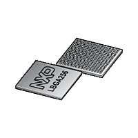
LPC1850FET256 NXP Semiconductors, LPC1850FET256 Datasheet - Page 121

LPC1850FET256
Manufacturer Part Number
LPC1850FET256
Description
The LPC1850FET256 is a high-performance, cost-effective Cortex-M3 microcontroller featuring 200 kB of SRAM, and advanced peripherals including Ethernet, High Speed USB 2
Manufacturer
NXP Semiconductors
Datasheet
1.LPC1810FBD144.pdf
(157 pages)
Available stocks
Company
Part Number
Manufacturer
Quantity
Price
Company:
Part Number:
LPC1850FET256
Manufacturer:
NXP
Quantity:
1 000
Part Number:
LPC1850FET256
Manufacturer:
NXP/恩智浦
Quantity:
20 000
Company:
Part Number:
LPC1850FET256,551
Manufacturer:
NXP Semiconductors
Quantity:
10 000
Part Number:
LPC1850FET256,551
Manufacturer:
NXP/恩智浦
Quantity:
20 000
NXP Semiconductors
12. ADC/DAC electrical characteristics
Table 25.
V
[1]
[2]
[3]
[4]
[5]
[6]
[7]
[8]
LPC1850_30_20_10
Preliminary data sheet
Symbol Parameter
V
C
E
E
E
E
E
R
R
f
f
clk(ADC)
c(ADC)
DDA(3V3)
IA
D
L(adj)
O
G
T
ia
vsi
i
The ADC is monotonic, there are no missing codes.
The differential linearity error (E
The integral non-linearity (E
appropriate adjustment of gain and offset errors. See
The offset error (E
ideal curve. See
The gain error (E
error, and the straight line which fits the ideal transfer curve. See
The absolute error (E
ADC and the ideal transfer curve. See
T
Input resistance R
amb
= 25 C; maximum sampling frequency f
over specified ranges; T
analog input voltage
analog input capacitance
differential linearity error
integral non-linearity
offset error
gain error
absolute error
voltage source interface
resistance
input resistance
ADC clock frequency
ADC conversion frequency 10-bit resolution; 11 clock
ADC characteristics
Figure
G
O
i
) is the relative difference in percent between the straight line fitting the actual transfer curve after removing offset
depends on the sampling frequency fs: R
) is the absolute difference between the straight line which fits the actual curve and the straight line which fits the
T
) is the maximum difference between the center of the steps of the actual transfer curve of the non-calibrated
35.
L(adj)
D
) is the peak difference between the center of the steps of the actual and the ideal transfer curve after
) is the difference between the actual step width and the ideal step width. See
amb
=
Conditions
2.7 V V
2.2 V V
2.7 V V
2.2 V V
2.7 V V
2.2 V V
2.7 V V
2.2 V V
2.7 V V
2.2 V V
see
cycles
2-bit resolution; 3 clock
cycles
Figure
40
All information provided in this document is subject to legal disclaimers.
Figure 36
s
C to +85
35.
= 4.5 MHz and analog input capacitance C
DDA(3V3)
DDA(3V3)
DDA(3V3)
DDA(3V3)
DDA(3V3)
DDA(3V3)
DDA(3V3)
DDA(3V3)
DDA(3V3)
DDA(3V3)
Rev. 3.1 — 15 December 2011
Figure
C; ADC frequency 4.5 MHz; unless otherwise specified.
3.6 V
< 2.7 V
3.6 V
< 2.7 V
3.6 V
< 2.7 V
3.6 V
< 2.7 V
3.6 V
< 2.7 V
i
35.
= 2 k + 1 / (f
Figure
35.
[1][2]
[7][8]
s
[3]
[4]
[5]
[6]
C
Min
0
-
-
-
-
-
-
-
-
-
-
-
-
-
-
-
ia
).
32-bit ARM Cortex-M3 microcontroller
LPC1850/30/20/10
Typ
-
-
0.8
1.0
0.8
1.5
0.15
0.15
0.3
0.35
3
4
-
-
-
-
ia
= 2 pF.
Max
V
2
-
-
-
-
-
-
-
-
-
-
1/(7 f
C
1.2
4.5
400
1.5
DDA(3V3)
ia
)
clk(ADC)
Figure
© NXP B.V. 2011. All rights reserved.
35.
%
MHz
kSamples/s
Unit
V
pF
LSB
LSB
LSB
LSB
LSB
LSB
%
LSB
LSB
k
M
MSamples/s
121 of 157


