1375192-6 TE Connectivity, 1375192-6 Datasheet

1375192-6

Manufacturer Part Number
1375192-6
Description
Manufacturer
TE Connectivity
Series
SL Seriesr
Datasheets

Specifications of 1375192-6

Product Type
Connector - Modular
Jack Type
RJ11 / RJ14 / RJ25
Wiring Pattern
USOC
Termination Style
110 Style Punch-Down
Keyed
No
Performance Category
Cat 3
Shielded
No
Number Of Positions
6
Netconnect Select System
No
Conductor O.d. (mm [in])
1.45 [0.057]
Mount Type
Panel Mount
Wire Range (solid) (mm [awg])
22-24
Wire Range (stranded) (mm² [awg])
24-26
110 Block Material
Polycarbonate
Contact Base Material
Phosphor Bronze
Contact Plating, Mating Area, Material
Gold
Contact Plating, Mating Area, Thickness (µm [?in])
1.27 [50]
Housing Color
Blue
Housing Material
Polycarbonate
Ul Flammability Rating
UL 94V-0
Dust Cover
Without
Rohs/elv Compliance
RoHS compliant, ELV compliant
Lead Free Solder Processes
Not relevant for lead free process
Rohs/elv Compliance History
Converted to comply with RoHS directive
Packaging Method
Poly Bag
Packaging Quantity
1
1.
1.1.
1.2.
1.3.
2.
2.1.
2.2.
©2011 Tyco Electronics Corporation,
a TE Connectivity Ltd. Company
All Rights Reserved
TE logo is a trademark.
SCOPE
Content
This specification covers perform ance, test and quality requirem ents for NETCONNECT* Category 3,
Category 5e and Category 6 SL Series unshielded 110 jacks, Category 5e and Category 6 SL Series
shielded 110 jacks and plugs. These assem blies are designed for installation into various outlet plates,
surface m ount boxes, panels, and other sim ilar type fittings. Jacks incorporate IDC term inals for
term inating both shielded or unshielded twisted pair com m unications cable. Jacks will accom m odate 22
- 24 AW G solid and 24 - 26 AW G stranded conductors. The m axim um conductor insulation diam eter is
1.45 m m [.057 in]. For large OD conductors 1.27 to 1.45 m m an external strain relief m ust be used. The
plugs accom m odate Category 6 cable and shielded or unshielded twisted pair cable with 23 - 24 AW G
solid, or 24 - 26 AW G stranded conductors. The m axim um conductor insulation diam eter is 1.00 m m
[.039 in] with a cable jacket diam eter between 4.7 and 7.0 m m [.185 and .276 in].
Qualification
W hen tests are perform ed on the subject product line, procedures specified in Figure 1 shall be used.
All inspections shall be perform ed using the applicable inspection plan and product drawing.
Successful qualification testing on the subject product line was com pleted on 01Nov02. The
Qualification Test Report num ber for this testing is 501-553. This docum entation is on file at and
available from Engineering Practices and Standards (EPS).
APPLICABLE DOCUM ENTS
The following docum ents form a part of this specification to the extent specified herein. Unless
otherwise specified, the latest edition of the docum ent applies. In the event of conflict between the
requirem ents of this specification and the product drawing, the product drawing shall take precedence.
In the event of conflict between the requirem ents of this specification and the referenced docum ents,
this specification shall take precedence.
TE Connectivity (TE) Docum ent
501-553: Qualification Test Report (NETCONNECT* SL Series Jacks and Category 6 Plugs)
Industrial Standards
!
!
!
!
!
EIA-364: Electrical Connector/Socket Test Procedures Including Environm ental Classifications
IEC 60068: Basic Environm ental Testing Procedures
IEC 60512: Electrom echanical Com ponents For Electronic Equipm ent; Basic Testing Procedures
and Measuring Methods Part 1: General
TIA/EIA-568-B.2: Com m ercial Building Telecom m unications Cabling Standard Part 2: Balanced
Twisted-Pair Cabling Com ponents
TIA-968-A: Telecom m unications, Telephone Term inal Equipm ent, Technical Requirem ents for
Connection of Term inal Equipm ent to the Telephone Network
| Indicates change
*Trademark
Product
Specification
NETCONNECT* SL Series Jacks and Category 6 Plugs
For latest revision, visit our website at www.te.com/documents.
For Regional Customer Service, visit our website at www.te.com
Other products, logos, and company names might be trademarks of their respective owners.
108-1990
11Mar11 Rev K
1 of 8
LOC B

Related parts for 1375192-6

1375192-6 Summary of contents

Page 1

... TIA-968-A: Telecom m unications, Telephone Term inal Equipm ent, Technical Requirem ents for Connection of Term inal Equipm ent to the Telephone Network ©2011 Tyco Electronics Corporation, | Indicates change a TE Connectivity Ltd. Company *Trademark All Rights Reserved TE logo is a trademark. For latest revision, visit our website at www.te.com/documents. ...

Page 2

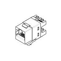
Reference Docum ents ! 108-1990-1: Product Specification (NETCONNECT* SL Series Category 3 Jacks) ! 108-1990-2: Product Specification (NETCONNECT* SL Series Category 5e Jacks) ! 108-1990-3: Product Specification (NETCONNECT* SL Series Category 6 Jacks) ! 109-197: Test Specification (TE Test ...

Page 3

Test Description Voltage proof. Vibration, jack-plug interface and IDC-wire interface. Mechanical shock, jack-plug interface. Durability, jack-plug interface using a 6 position plug. Durability, jack-plug interface. Plug insertion force, jack-plug interface. Plug withdrawal force, jack-plug interface. Plug retention in jack, jack-plug ...

Page 4

Test Description Term ination tensile strength, horizontal, IDC-wire interface. Term ination tensile strength, vertical, IDC-wire interface. Durability repeated, IDC-wire interface. Therm al shock, IDC-wire interface. Therm al shock, jack-plug interface. See Note. Hum idity/tem perature cycling, IDC- wire interface. Hum ...

Page 5

Test Description Mixed flowing gas, jack-plug interface. Shall meet visual requirements, show no physical damage, and meet requirements of additional NOTE tests as specified in the Product Qualification and Requalification Test Sequence shown in Figure 2. 3.6. Product Qualification and ...

Page 6

QUALITY ASSURANCE PROVISIONS 4.1. Qualification Testing A. Specim en Selection Plugs and jacks shall be prepared in accordance with applicable Instruction Sheet and shall be selected at random from current production. Test groups and 5 ...

Page 7

Termination resistance of this assembly consists of plug to jack contact resistance plus NOTE printed circuit board trace plus IDC terminal to discrete wire contact resistance. Printed circuit board trace length varies with each jack position, therefore, significant variations ...

Page 8

Rev K Figure 5 Term ination Tensile Strength Vertical Pull 108-1990 ...

Related keywords