2-406372-6 TE Connectivity, 2-406372-6 Datasheet

2-406372-6

Manufacturer Part Number
2-406372-6
Description
Manufacturer
TE Connectivity
Series
110Connectr
Datasheets

Specifications of 2-406372-6

Product Type
Connector - Modular
Jack Type
RJ45
Wiring Pattern
Universal
Termination Style
110 Style Punch-Down
Keyed
No
Performance Category
Cat 5e
Stuffer Cap Material
Polyphenylene Oxide
Stuffer Cap Color
Gray
Shielded
No
Solder Tail Contact Plating
Tin-Lead over Nickel
Number Of Positions
8
Netconnect Select System
No
Conductor O.d. (mm [in])
1.27 [0.050]
Mount Type
Panel Mount
Wire Range (solid) (mm [awg])
22-26
Wire Range (stranded) (mm² [awg])
22-26
110 Block Material
Polycarbonate
Contact Base Material
Phosphor Bronze
Contact Plating, Mating Area, Material
Gold
Contact Plating, Mating Area, Thickness (µm [?in])
1.27 [50]
Housing Color
Blue
Housing Material
Polyphenylene Oxide
Ul Flammability Rating
UL 94V-0
Dust Cover
Without
Rohs/elv Compliance
RoHS compliant, ELV compliant
Lead Free Solder Processes
Wave solder capable to 240°C
Rohs/elv Compliance History
Converted to comply with RoHS directive
Packaging Method
Poly Bag
Packaging Quantity
25
1.
1.1.
1.2.
2.
2.1.
2.2.
3.
3.1.
©2011 Tyco Electronics Corporation,
a TE Connectivity Ltd. Company
All Rights Reserved
TE logo is a trademark.
SCOPE
Content
This specification covers performance, tests and quality requirements for TE Connectivity (TE) Category
3 and Category 5 110 panel mount modular jacks. These assemblies are designed for panel mounting
and provide insulation displacing 110 punchdown blocks for terminating both shielded and unshielded
twisted pair conductors to the jacks. 110 blocks are designed to terminate 22 to 26 AWG solid or
stranded conductors having a maximum overall diameter of .050. Jacks are available in fully shielded,
unshielded and grounded styles.
Qualification
When tests are performed on subject product line, procedures specified in 109 Series Test
Specifications shall be used. All inspections shall be performed using applicable inspection plan and
product drawing.
APPLICABLE DOCUMENTS
The following documents constitute a part of this specification to the extent specified herein. In the
event of conflict between requirements of this specification and product drawing, product drawing shall
take precedence. In the event of conflict between requirements of this specification and referenced
documents, this specification shall take precedence.
TE Documents
!
!
!
!
!
Commercial Specifications
!
!
!
REQUIREMENTS
Design and Construction
Product shall be of the design, construction and physical dimensions specified on the applicable product
drawing.
109-1: General Requirements For Test Specifications
109 Series: Test Specifications as indicated in Figure 1
108-1588: Product Specification (110 Connection Block)
408-3354: Instruction Sheet (110 Panel Mount Jack)
501-202: Qualification Test Report
EIA/TIA-TSB40-A: Transmission Specifications for Unshielded Twisted Pair Connecting Hardware
FCC Rules For Registration Of Telephone Equipment, Part 68, Subpart F, Connectors
UL File E81956 Volume 1, Section 12: Communication Circuit Accessories
| Indicates change
*Trademark
Product
Specification
Jack, Modular, 110 Panel Mount
For latest revision, visit our website at www.te.com/documents.
For Regional Customer Service, visit our website at www.te.com
Other products, logos, and company names might be trademarks of their respective owners.
108-1389
11Mar11 Rev B
1 of 6
LOC B

Related parts for 2-406372-6

2-406372-6 Summary of contents

Page 1

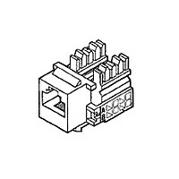
... Category 5 110 panel mount modular jacks. These assemblies are designed for panel mounting and provide insulation displacing 110 punchdown blocks for terminating both shielded and unshielded twisted pair conductors to the jacks. 110 blocks are designed to terminate AWG solid or stranded conductors having a maximum overall diameter of .050. Jacks are available in fully shielded, unshielded and grounded styles ...

Page 2

... Emission levels can be affected by many variables such as cable type, cable length, grounding method and test setup. Contribution of a shielded connector to overall shielding will vary with each application. Typically, a shielded modular plug/jack interface may be expected to improve shielding effectiveness approximately compared to an unshielded interface. ! Frequency range: • ...

Page 3

... Hz traversed in 1 minute at .06 inches total excursion. 15 minutes in each of 3 mutually perpendicular planes. TE Spec 109-50. Apply axial load of 20 pounds to plug housing at rate of .5 inch per minute with plug mated in jack and latch engaged. TE Spec 109-26-1. Subject mated jack and plug assembly to 50 G's half-sine shock pulses of 11 milliseconds duration ...

Page 4

... Housing panel retention. Thermal shock. Humidity-temperature cycling. Mixed flowing gas. Temperature life. Shall meet visual requirements, show no physical damage and shall meet requirements of NOTE additional tests specified in Test Sequence in Figure 2. Rev B Requirement 20 pounds minimum. ENVIRONMENTAL Insulation resistance. Termination resistance, dry circuit final. ...

Page 5

... Sheets and shall be selected at random from current production. All test groups shall consist of 10, 110 panel mount jacks and 10 terminated plugs. B. Test sequence. Qualification inspection shall be verified by testing samples as specified in Figure 2. 4.2. Requalification Testing If changes significantly affecting form, fit or function are made to product or manufacturing process, product assurance shall coordinate requalification testing consisting of all or part of original testing sequence as determined by development/product, quality and reliability engineering ...

Page 6

... Printed circuit board trace length varies with each jack position, therefore, significant variations in termination resistance readings can be expected within each jack assembly. (b) Millivolt drop (resistance) due to 6 inch and 2 inch wire lengths shall be subtracted from all readings. Rev B ...

Related keywords