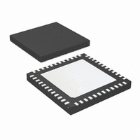
LMH0036SQE/NOPB National Semiconductor, LMH0036SQE/NOPB Datasheet - Page 10

LMH0036SQE/NOPB
Manufacturer Part Number
LMH0036SQE/NOPB
Description
IC RECLOCKER SD 4:1 MUX 48LLP
Manufacturer
National Semiconductor
Type
Reclockerr
Datasheet
1.LMH0036SQENOPB.pdf
(14 pages)
Specifications of LMH0036SQE/NOPB
Applications
SDTV/HDTV
Mounting Type
Surface Mount
Package / Case
48-LLP
Operating Temperature (max)
85C
Operating Temperature (min)
-40C
Pin Count
48
Mounting
Surface Mount
Lead Free Status / RoHS Status
Lead free / RoHS Compliant
Other names
LMH0036SQE/NOPBTR
www.national.com
Application Information
Figure 4 shows a application circuit for the LMH0036.
BYPASS/AUTO BYPASS has an internal pulldown to enable
Auto Bypass mode by default. This pin may be pulled high to
force the LMH0036 to bypass all data.
OUTPUT MUTE has an internal pullup to enable the outputs
by default. This pin may be pulled low to mute the outputs.
The XTAL IN/EXT CLK and XTAL OUT pins are shown with
a 27 MHz crystal and the proper loading. The crystal should
match the parameters described in Table 3. Alternately, a
27MHz LVCMOS compatible clock signal may be input to
XTAL IN/EXT CLK.
The active high LOCK DETECT output provides an indication
that proper data is being received and the PLL is locked.
The SD output may be used to drive the SD/HD pin of an SDI
cable driver (such as the LMH0002) in order to properly set
the cable driver’s edge rate for SMPTE compliance. It defaults
to low when the LMH0036 is not locked.
SCO_EN has an internal pulldown to set the second output
(SCO/SDO2) to output data. This pin may be pulled high to
set the second output as a serial clock.
FIGURE 4. Application Circuit
10
The external loop filter capacitor (between LF1 and LF2)
should be 56 nF. This is the only supported value; the loop
filter capacitor should not be changed.
SEL0 and SEL1 have internal pulldowns to select the SDI0
input by default.
The inputs are LVPECL compatible. The LMH0036 has a
wide input common mode range and in most cases the input
should be DC coupled. For DC coupling, the inputs must be
kept within the common mode range specified in DC Electrical
Characteristics.
Figure 5 shows an example of a DC coupled interface be-
tween the LMH0074 cable equalizer and the LMH0036. The
LMH0074 output common mode voltage and voltage swing
are within the range of the input common mode voltage and
voltage swing of the LMH0036. All that is required is a 100Ω
differential termination as shown. The resistor should be
placed as close as possible to the LMH0036 input. If desired,
this network may be terminated with two 50Ω resisters and a
center tap capacitor to ground in place of the single 100Ω
resistor.
30003104


