74AHCT1G00GV,125 NXP Semiconductors, 74AHCT1G00GV,125 Datasheet
74AHCT1G00GV,125
Specifications of 74AHCT1G00GV,125
74AHCT1G00GV
935271648125


Related parts for 74AHCT1G00GV,125


74AHCT1G00GV,125 Summary of contents
Page 1
NAND gate Rev. 06 — 30 May 2007 1. General description 74AHC1G00 and 74AHCT1G00 are high-speed Si-gate CMOS devices. They provide a 2-input NAND function. The AHC device has CMOS input switching levels and supply voltage range ...
Page 2
... NXP Semiconductors 4. Marking Table 2. Marking codes Type number 74AHC1G00GW 74AHC1G00GV 74AHCT1G00GW 74AHCT1G00GV 5. Functional diagram mna097 Fig 1. Logic symbol 6. Pinning information 6.1 Pinning Fig 4. Pin configuration 6.2 Pin description Table 3. Pin description Symbol Pin GND 74AHC_AHCT1G00_6 Product data sheet 74AHC1G00; 74AHCT1G00 ...
Page 3
... NXP Semiconductors 7. Functional description Table 4. Function table H = HIGH voltage level LOW voltage level Inputs Limiting values Table 5. Limiting values In accordance with the Absolute Maximum Rating System (IEC 60134). Symbol Parameter V supply voltage CC V input voltage I I input clamping current IK I output clamping current ...
Page 4
... NXP Semiconductors 10. Static characteristics Table 7. Static characteristics Voltages are referenced to GND (ground = 0 V). Symbol Parameter Conditions For type 74AHC1G00 V HIGH-level input voltage LOW-level input voltage HIGH-level output voltage 4.0 mA 8.0 mA LOW-level output voltage 4.0 mA 8.0 mA input leakage GND ...
Page 5
... NXP Semiconductors Table 7. Static characteristics Voltages are referenced to GND (ground = 0 V). Symbol Parameter Conditions I supply current 5 additional per input pin supply current other inputs input I capacitance 11. Dynamic characteristics Table 8. Dynamic characteristics GND = 3.0 ns. For test circuit see r f Symbol Parameter Conditions ...
Page 6
... NXP Semiconductors 12. Waveforms Measurement points are given in Fig 5. The inputs (A and B) to output (Y) propagation delays Table 9. Measurement point Type Input V I 74AHC1G00 GND to V 74AHCT1G00 GND to 3.0 V Test data is given in Table 8. Definitions for test circuit Load capacitance including jig and probe capacitance. ...
Page 7
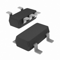
... NXP Semiconductors 13. Package outline TSSOP5: plastic thin shrink small outline package; 5 leads; body width 1. DIMENSIONS (mm are the original dimensions UNIT max. 0.1 1.0 mm 1.1 0.15 0 0.8 Note 1. Plastic or metal protrusions of 0.15 mm maximum per side are not included. OUTLINE VERSION IEC SOT353-1 Fig 7 ...
Page 8
... NXP Semiconductors Plastic surface-mounted package; 5 leads DIMENSIONS (mm are the original dimensions UNIT 0.100 0.40 1.1 0.26 mm 0.013 0.25 0.9 0.10 OUTLINE VERSION IEC SOT753 Fig 8. Package outline SOT753 (SC-74A) 74AHC_AHCT1G00_6 Product data sheet 74AHC1G00; 74AHCT1G00 scale 3.1 1.7 3.0 0.6 0.95 2 ...
Page 9
... Release date 74AHC_AHCT1G00_6 20070530 • Modifications: The format of this data sheet has been redesigned to comply with the new identity guidelines of NXP Semiconductors. • Legal texts have been adapted to the new company name where appropriate. • Package SOT353 changed to SOT353-1 in • ...
Page 10
... For detailed and full information see the relevant full data sheet, which is available on request via the local NXP Semiconductors sales office. In case of any inconsistency or conflict with the short data sheet, the full data sheet shall prevail ...
Page 11
... NXP Semiconductors 18. Contents 1 General description . . . . . . . . . . . . . . . . . . . . . . 1 2 Features . . . . . . . . . . . . . . . . . . . . . . . . . . . . . . . 1 3 Ordering information . . . . . . . . . . . . . . . . . . . . . 1 4 Marking . . . . . . . . . . . . . . . . . . . . . . . . . . . . . . . . 2 5 Functional diagram . . . . . . . . . . . . . . . . . . . . . . 2 6 Pinning information . . . . . . . . . . . . . . . . . . . . . . 2 6.1 Pinning . . . . . . . . . . . . . . . . . . . . . . . . . . . . . . . 2 6.2 Pin description . . . . . . . . . . . . . . . . . . . . . . . . . 2 7 Functional description . . . . . . . . . . . . . . . . . . . 3 8 Limiting values Recommended operating conditions Static characteristics Dynamic characteristics . . . . . . . . . . . . . . . . . . 5 12 Waveforms . . . . . . . . . . . . . . . . . . . . . . . . . . . . . 6 13 Package outline . . . . . . . . . . . . . . . . . . . . . . . . . 7 14 Abbreviations ...