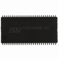
IS42S16400F-6TL ISSI, Integrated Silicon Solution Inc, IS42S16400F-6TL Datasheet - Page 12

IS42S16400F-6TL
Manufacturer Part Number
IS42S16400F-6TL
Description
IC SDRAM 64MBIT 166MHZ 54TSOP
Manufacturer
ISSI, Integrated Silicon Solution Inc
Type
SDRAMr
Specifications of IS42S16400F-6TL
Format - Memory
RAM
Memory Type
SDRAM
Memory Size
64M (4M x 16)
Speed
166MHz
Interface
Parallel
Voltage - Supply
3 V ~ 3.6 V
Operating Temperature
0°C ~ 70°C
Package / Case
54-TSOP II
Organization
4Mx16
Density
64Mb
Address Bus
14b
Access Time (max)
6/5.4ns
Maximum Clock Rate
166MHz
Operating Supply Voltage (typ)
3.3V
Package Type
TSOP-II
Operating Temp Range
0C to 70C
Operating Supply Voltage (max)
3.6V
Operating Supply Voltage (min)
3V
Supply Current
130mA
Pin Count
54
Mounting
Surface Mount
Operating Temperature Classification
Commercial
Data Bus Width
16 bit
Maximum Clock Frequency
166 MHz
Access Time
6 ns, 5.4 ns
Supply Voltage (max)
3.6 V
Supply Voltage (min)
3 V
Maximum Operating Current
130 mA
Maximum Operating Temperature
+ 70 C
Minimum Operating Temperature
0 C
Mounting Style
SMD/SMT
Lead Free Status / RoHS Status
Lead free / RoHS Compliant
Other names
706-1075
IS42S16400F-6TL
IS42S16400F-6TL
Available stocks
Company
Part Number
Manufacturer
Quantity
Price
Part Number:
IS42S16400F-6TL
Manufacturer:
ISSI
Quantity:
20 000
Company:
Part Number:
IS42S16400F-6TLI
Manufacturer:
ISSI
Quantity:
5 530
Company:
Part Number:
IS42S16400F-6TLI
Manufacturer:
ISSI
Quantity:
6 250
Company:
Part Number:
IS42S16400F-6TLI
Manufacturer:
ISSI
Quantity:
1 831
IS42S16400F
IC42S16400F
DC ELECTRICAL CHARACTERISTICS
Notes:
1. These are the values at the minimum cycle time. Since the currents are transient, these values decrease as the cycle time in-
2. Icc
3. Input signal chnage once per 30ns.
12
Symbol Parameter
i
i
V
V
i
i
I
i
I
i
i
i
I
i
i
i
il
ol
cc1
cc2p
cc2ps
cc2N
cc2Ns
cc3p
cc3ps
cc3N
cc3Ns
cc4
cc5
cc6
oh
ol
creases. Also note that a bypass capacitor of at least 0.01 µF should be inserted between V
to suppress power supply voltage noise (voltage drops) due to these transient currents.
(3)
(3)
1
and Icc
Input Leakage Current
Output Leakage Current
Output High Voltage Level
Output Low Voltage Level
Operating Current
Precharge Standby Current
(In Power-Down Mode)
Precharge Standby Current
(In Non Power-Down Mode)
Active Standby Current
(In Power-Down Mode)
Active Standby Current
(In Non Power-Down Mode)
Operating Current
(In Burst Mode)
Auto-Refresh Current
Self-Refresh Current
4
depend on the output load. The maximum values for Icc
(1)
(1,2)
Test Condition
0V ≤ V
the tested pin at 0V
Output is disabled, 0V ≤ V
i
i
One Bank Operation,
Burst Length=1
t
I
CKE ≤ V
CKE ≥ V
CKE ≤ V
CKE ≥ V
t
I
BL = 4; 4 banks activated
t
t
CKE ≤ 0.2V
out
out
rc
out
ck
out
rc
clk
≥ t
= t
= t
= t
= –2 mA
= +2 mA
= 0mA
= 0mA
rc
ck
rc
iN
clk
il
ih
il
ih
≤ V
(min.)
(
(
miN
miN
(
(
(
(
(
max
miN
miN
miN
max
DD
(Recommended Operation Conditions unless otherwise noted.)
)
)
)
, with pins other than
)
)
)
)
out
CAS latency = 3 Com.
CAS latency = 3 Com.
1
CAS latency = 3Com.
≤ V
t
t
t
t
t
t
t
t
ck
ck
ck
ck
ck
ck
ck
ck
and Icc
Integrated Silicon Solution, Inc. — www.issi.com
DD
= 15ns
= ∞
= 15ns
= ∞
= 10ns
= ∞
= 15ns
= ∞
4
are obtained with the output open state.
Com.
Com.
Com.
Com.
Com.
Com.
Com.
Com.
Com.
Com.
Com.
Com.
Ind.
Ind.
Ind.
Ind.
Ind.
Ind.
Ind.
Ind.
Ind.
Ind.
Ind.
Ind.
Ind.
Ind.
Ind.
Speed
DD
—
—
—
—
—
—
—
—
—
—
—
—
—
—
—
-5
-6
-7
-5
-6
-7
-5
-6
-7
-5
-6
-7
-5
-6
-7
-5
-6
-7
and GND for each memory chip
Min.
2.4
–5
–5
—
—
—
—
—
—
—
—
—
—
—
—
—
—
—
—
—
—
—
—
—
—
—
—
—
—
—
—
—
—
—
—
—
—
Max.
110
180
155
145
140
130
100
150
140
110
160
150
130
180
170
150
0.4
95
85
20
15
15
30
25
25
—
5
5
2
4
2
3
7
7
5
5
2
03/19/08
Unit
mA
mA
mA
mA
mA
mA
mA
mA
mA
mA
mA
mA
mA
mA
mA
mA
mA
mA
mA
mA
mA
mA
mA
mA
mA
mA
mA
mA
mA
mA
mA
mA
mA
µA
µA
Rev. A
V
V


