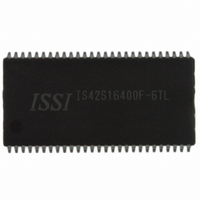
IS42S16400F-6TL ISSI, Integrated Silicon Solution Inc, IS42S16400F-6TL Datasheet - Page 31

IS42S16400F-6TL
Manufacturer Part Number
IS42S16400F-6TL
Description
IC SDRAM 64MBIT 166MHZ 54TSOP
Manufacturer
ISSI, Integrated Silicon Solution Inc
Type
SDRAMr
Specifications of IS42S16400F-6TL
Format - Memory
RAM
Memory Type
SDRAM
Memory Size
64M (4M x 16)
Speed
166MHz
Interface
Parallel
Voltage - Supply
3 V ~ 3.6 V
Operating Temperature
0°C ~ 70°C
Package / Case
54-TSOP II
Organization
4Mx16
Density
64Mb
Address Bus
14b
Access Time (max)
6/5.4ns
Maximum Clock Rate
166MHz
Operating Supply Voltage (typ)
3.3V
Package Type
TSOP-II
Operating Temp Range
0C to 70C
Operating Supply Voltage (max)
3.6V
Operating Supply Voltage (min)
3V
Supply Current
130mA
Pin Count
54
Mounting
Surface Mount
Operating Temperature Classification
Commercial
Data Bus Width
16 bit
Maximum Clock Frequency
166 MHz
Access Time
6 ns, 5.4 ns
Supply Voltage (max)
3.6 V
Supply Voltage (min)
3 V
Maximum Operating Current
130 mA
Maximum Operating Temperature
+ 70 C
Minimum Operating Temperature
0 C
Mounting Style
SMD/SMT
Lead Free Status / RoHS Status
Lead free / RoHS Compliant
Other names
706-1075
IS42S16400F-6TL
IS42S16400F-6TL
Available stocks
Company
Part Number
Manufacturer
Quantity
Price
Part Number:
IS42S16400F-6TL
Manufacturer:
ISSI
Quantity:
20 000
Company:
Part Number:
IS42S16400F-6TLI
Manufacturer:
ISSI
Quantity:
5 530
Company:
Part Number:
IS42S16400F-6TLI
Manufacturer:
ISSI
Quantity:
6 250
Company:
Part Number:
IS42S16400F-6TLI
Manufacturer:
ISSI
Quantity:
1 831
IS42S16400F
IC42S16400F
PRECHARGE
The PRECHARGE command (see figure) is used to deac-
tivate the open row in a particular bank or the open row in
all banks.The bank(s) will be available for a subsequent row
access some specified time (t
command is issued. Input A10 determines whether one or
all banks are to be precharged, and in the case where only
one bank is to be precharged, inputs BA0, BA1 select the
bank. When all banks are to be precharged, inputs BA0,
BA1 are treated as “Don’t Care.” Once a bank has been
precharged, it is in the idle state and must be activated
prior to any READ or WRITE commands being issued to
that bank.
Integrated Silicon Solution, Inc. — www.issi.com
Rev. A
03/19/08
POWER-DOWN
Power-down occurs if CKE is registered LOW coincident
with a NOP or COMMAND INHIBIT when no accesses
are in progress. If power-down occurs when all banks are
idle, this mode is referred to as precharge power-down;
if power-down occurs when there is a row active in either
bank, this mode is referred to as active power-down.
Entering power-down deactivates the input and output
buffers, excluding CKE, for maximum power savings while
in standby. The device may not remain in the power-down
state longer than the refresh period (64ms) since no refresh
operations are performed in this mode.
The power-down state is exited by registering a NOP or
COMMAND INHIBIT and CKE HIGH at the desired clock
edge (meeting t
POWER-DOWN
cks
COMMAND
). See figure below.
CKE
CLK
All banks idle
Enter power-down mode
rp
) after the PRECHARGE
t
NOP
CKS
Input buffers gated off
PRECHARGE Command
Exit power-down mode
BA0, BA1
A0-A9, A11
CKE
RAS
CAS
CLK
A10
WE
CS
≥ t
HIGH - Z
CKS
NOP
DON'T CARE
BANK ADDRESS
BANK SELECT
ACTIVE
ALL BANKS
t
t
t
RCD
RAS
RC
31


