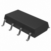
S-24CS01AFJ-TB-G Seiko Instruments, S-24CS01AFJ-TB-G Datasheet - Page 26

S-24CS01AFJ-TB-G
Manufacturer Part Number
S-24CS01AFJ-TB-G
Description
IC EEPROM 1KBIT 400KHZ 8SOP
Manufacturer
Seiko Instruments
Datasheet
1.S-24CS01AFT-TB-G.pdf
(47 pages)
Specifications of S-24CS01AFJ-TB-G
Format - Memory
EEPROMs - Serial
Memory Type
EEPROM
Memory Size
1K (128 x 8)
Speed
400kHz
Interface
I²C, 2-Wire Serial
Voltage - Supply
1.8 V ~ 5.5 V
Operating Temperature
-40°C ~ 85°C
Package / Case
8-SOP
Lead Free Status / RoHS Status
Lead free / RoHS Compliant
Available stocks
Company
Part Number
Manufacturer
Quantity
Price
Company:
Part Number:
S-24CS01AFJ-TB-G
Manufacturer:
SEIKO
Quantity:
576
26
2-WIRE CMOS SERIAL E
S-24CS01A/02A/04A/08A
6. Data hold time (t
7. SDA pin and SCL pin noise suppression time
If SCL and SDA of the E
condition from being mistakenly recognized due to the effect of noise. If a start/stop condition is mistakenly
recognized during communication, the E
It is recommended that SDA is delayed from the falling edge of SCL by 0.3 µ s minimum in the S-
24CS01A/02A/04A/08A. This is to prevent time lag caused by the load of the bus line from generating the
stop (or start) condition.
The S-24CS01A/02A/04A/08A includes a built-in low-pass filter to suppress noise at the SDA and SCL
pins. This means that if the power supply voltage is 5.0 V, noise with a pulse width of 160 ns or less can
be suppressed.
The guaranteed for details, refer to noise suppression time (t
Noise suppression time (t
Figure 31 Noise Suppression Time for SDA and SCL Pins
HD.DAT
[ns]
= 0 ns)
SDA
SCL
2
PROM are changed at the same time, it is necessary to prevent the start/stop
2
PROM
I
) Max.
Figure 30 E
Seiko Instruments Inc.
2
PROM enters the standby status.
300
200
100
2
PROM Data Hold Time
t
HD.DAT
Power supply voltage (V
= 0.3 µs Min.
2
I
) in Table 12 .
[V]
3
4
CC
)
5
Rev.4.5
_00


