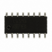
L6591 STMicroelectronics, L6591 Datasheet - Page 33

L6591
Manufacturer Part Number
L6591
Description
IC CTRLR PWM PROG CM HV 16SOIC
Manufacturer
STMicroelectronics
Specifications of L6591
Output Isolation
Isolated
Frequency Range
168 ~ 192kHz
Voltage - Input
8.7 ~ 22 V
Power (watts)
750mW
Operating Temperature
-40°C ~ 150°C
Package / Case
16-SOIC (0.154", 3.90mm Width)
Output Voltage
5 V
Input Voltage
25 V
Operating Temperature Range
- 40 C to + 150 C
Mounting Style
SMD/SMT
Duty Cycle (max)
50 %
For Use With
497-8335 - BOARD EVAL FOR L6591
Lead Free Status / RoHS Status
Lead free / RoHS Compliant
Other names
497-8286
Available stocks
Company
Part Number
Manufacturer
Quantity
Price
Part Number:
L6591
Manufacturer:
ST
Quantity:
20 000
Part Number:
L6591TR
Manufacturer:
ST
Quantity:
20 000
L6591
Application information
Figure 51. Soft-start pin operation under different operating conditions
While in case of feedback loop failure the system must be stopped quickly to prevent the
output voltage from reaching too high values, an overload or a short circuit does not
generally need such fast intervention. The L6591 makes it easier to handle such conditions:
the 2 V clamp on the SS pin is removed and a second internal current generator I
= I
SS2
SS1
/4 keeps on charging Css. If the voltage reaches 5 V the IC will be disabled, if it is allowed to
reach 2 V
over 5 V, the IC will be latched off. In the former case the resulting behavior will
BE
be identical to that under short circuit illustrated in
Figure 46
; in the latter case the result will
be identical to that of
Figure 47
. The time delay before stopping switching upon overload is:
Equation 9
C
=
SS
T
12
delay
I
SS
1
If the overload disappears before the SS voltage reaches 5 V the I
generator will be
SS2
turned off and the voltage gradually brought back down to 2 V. A diode, with the anode to the
SS pin and the cathode connected to the VREF pin (#6) allows the designer to select either
an auto-restart mode or a latch-mode behavior upon overload.
If latch-mode behavior is desired also for converter ’ s short circuit, make sure that the supply
voltage of the IC never falls below the UVLO threshold before activating the latch.
Figure 20
shows soft-start pin behavior under different operating conditions.
Figure 52
shows a typical high-power adapter application that uses the L6591 in conjunction
with the L6563 PFC controller.
Doc ID 14821 Rev 5
33/41


