NCP1028P065G ON Semiconductor, NCP1028P065G Datasheet - Page 24
NCP1028P065G
Manufacturer Part Number
NCP1028P065G
Description
IC SWIT HV 8DIP
Manufacturer
ON Semiconductor
Datasheet
1.NCP1028P065G.pdf
(29 pages)
Specifications of NCP1028P065G
Output Isolation
Isolated
Frequency Range
58.5 ~ 71.5kHz
Voltage - Input
7.2 ~ 10 V
Voltage - Output
700V
Power (watts)
25W
Operating Temperature
0°C ~ 150°C
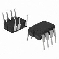
Package / Case
8-DIP (0.300", 7.62mm), 7 Leads
Lead Free Status / RoHS Status
Lead free / RoHS Compliant
Available stocks
Company
Part Number
Manufacturer
Quantity
Price

Part Number:
NCP1028P065G
Manufacturer:
ON/安森美
Quantity:
20 000


5.0 V/3.0 A Universal Mains Power Supply
universal mains SMPS up to 15 W of continuous power,
provided that the chip power dissipation is well under
control. That is to say that average power calculations and
measurements have been carried and correlated. The
design of an SMPS around a monolithic device does not
differ from that of a standard circuit using a controller and
a MOSFET. However, one needs to be aware of certain
characteristics specific of monolithic devices. Let us
follow the steps:
drain at the switch opening cannot be larger than the input
voltage. When selecting components, you thus must adopt
a turn ratio which adheres to the following equation:
since we operate from a 120 V DC rail while delivering
5.0 V, we can select a reflected voltage of 110 V
DC maximum: 120-110 > 0. Therefore, the turn ratio
Np:Ns must be smaller than
calculation.
N(V out ) V f ) t V in, min t Vin min
Np : Ns t 19
50.0
50.0
350
250
150
Due to its low R
As a result, the Flyback voltage which is reflected on the
Figure 42. The reflected voltage shall always be greater
-
than the minimum input voltage to avoid the forward
2. Lateral MOSFETs have a poorly doped
body-diode which naturally limits their ability to
sustain the avalanche. A traditional RCD
clamping network shall thus be installed to
protect the MOSFET. In some low power
applications, a simple capacitor can also be used
since
inductance,
node (which is increased by the capacitor you
will wire between drain and source), N the Np:Ns
) I peak
1.004M
biasing of the MOSFET body-diode.
Vdrain max + V in ) N (V out ) V f )
. We will see later on how it affects the
1.011M
C tot
C
L f
DS(on)
tot
the total capacitance at the drain
, the NCP1028 can be used in
(eq. 15)
1.018M
V out ) V f
V in
> 0 !!
, where L
(eq. 14)
1.025M
+ 110
5 ) 1
f
is the leakage
. In our case,
1.032M
+ 18.3
http://onsemi.com
NCP1028
or
24
V
V
V
V
Operating mode is CCM
h = 0.8
d max +
•
in
in
out
out
Small K: deep CCM, implying a large primary
inductance, a low bandwidth and a large leakage
inductance.
min = 120 Vdc
max = 375 Vdc
1. The lateral MOSFET body-diode shall never be
3. Calculate the maximum operating duty-cycle for
4. To obtain the primary inductance, we have the
= 5.0 V
= 15 W
forward biased, either during startup (because of a
large leakage inductance) or in normal operation
as shown by Figure 42. This condition sets the
maximum voltage that can be reflected during
turn ratio,
secondary diode forward drop and finally,
the maximum peak current. Worse case occurs
when the SMPS is very close to regulation, e.g.
the
pushed to the maximum. For this design, we have
selected our maximum voltage around 650 V (at
V
clamp installed from the drain to the bulk
voltage. We will see how to calculate it later on.
this flyback converter operated in CCM:
choice between two equations:
defines the amount of ripple we want in CCM
(see Figure 43).
L +
in
NV out ) V in, min
V
= 375 Vdc). This voltage is given by the RCD
out
f SW KP in
(V in d) 2
Figure 43. Primary Inductance Current
NV out
target is almost reached and
V
out
the output voltage,
(eq. 17)
Evolution in CCM
+
1 )
, where
1
V in,min
NV out
K +
+ 0.49
V
f
DI L
I
I 1
the
peak
and
I
is still
peak
(eq. 16)
t
off
.
Related parts for NCP1028P065G
Image
Part Number
Description
Manufacturer
Datasheet
Request
R

Part Number:
Description:
High?voltage Switcher For Medium Power Offline Smps
Manufacturer:
ON Semiconductor
Datasheet:
Part Number:
Description:
ON Semiconductor [VOLTAGE REGULATOR]
Manufacturer:
ON Semiconductor
Datasheet:
Part Number:
Description:
357-036-542-201 CARDEDGE 36POS DL .156 BLK LOPRO
Manufacturer:
ON Semiconductor
Datasheet:
Part Number:
Description:
357-036-542-201 CARDEDGE 36POS DL .156 BLK LOPRO
Manufacturer:
ON Semiconductor
Datasheet:
Part Number:
Description:
357-036-542-201 CARDEDGE 36POS DL .156 BLK LOPRO
Manufacturer:
ON Semiconductor
Datasheet:
Part Number:
Description:
357-036-542-201 CARDEDGE 36POS DL .156 BLK LOPRO
Manufacturer:
ON Semiconductor
Datasheet:
Part Number:
Description:
357-036-542-201 CARDEDGE 36POS DL .156 BLK LOPRO
Manufacturer:
ON Semiconductor
Datasheet:
Part Number:
Description:
357-036-542-201 CARDEDGE 36POS DL .156 BLK LOPRO
Manufacturer:
ON Semiconductor
Datasheet:
Part Number:
Description:
357-036-542-201 CARDEDGE 36POS DL .156 BLK LOPRO
Manufacturer:
ON Semiconductor
Datasheet:
Part Number:
Description:
357-036-542-201 CARDEDGE 36POS DL .156 BLK LOPRO
Manufacturer:
ON Semiconductor
Datasheet:
Part Number:
Description:
357-036-542-201 CARDEDGE 36POS DL .156 BLK LOPRO
Manufacturer:
ON Semiconductor
Datasheet:
Part Number:
Description:
357-036-542-201 CARDEDGE 36POS DL .156 BLK LOPRO
Manufacturer:
ON Semiconductor
Datasheet:
Part Number:
Description:
Manufacturer:
ON Semiconductor
Datasheet:
Part Number:
Description:
Manufacturer:
ON Semiconductor
Datasheet: