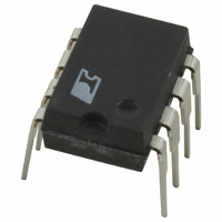
TOP209P Power Integrations, TOP209P Datasheet - Page 11

TOP209P
Manufacturer Part Number
TOP209P
Description
IC OFFLINE SWIT PWM OCP HV 8DIP
Manufacturer
Power Integrations
Series
TOPSwitch®r
Type
Off Line Switcherr
Datasheet
1.TOP210PN.pdf
(16 pages)
Specifications of TOP209P
Output Isolation
Isolated
Frequency Range
55 ~ 85kHz
Voltage - Output
700V
Power (watts)
2W
Operating Temperature
-40°C ~ 150°C
Package / Case
8-DIP (0.300", 7.62mm)
Output Voltage
5.8 V
Input / Supply Voltage (max)
265 VAC
Input / Supply Voltage (min)
85 VAC
Duty Cycle (max)
70 %
Switching Frequency
70 KHz
Supply Current
1.2 mA
Operating Temperature Range
- 40 C to + 150 C
Mounting Style
Through Hole
Lead Free Status / RoHS Status
Contains lead / RoHS non-compliant
Available stocks
Company
Part Number
Manufacturer
Quantity
Price
Company:
Part Number:
TOP209P
Manufacturer:
MICROELE
Quantity:
6 000
Part Number:
TOP209P
Manufacturer:
PI
Quantity:
20 000
Company:
Part Number:
TOP209PFI
Manufacturer:
POWER
Quantity:
15 000
Part Number:
TOP209PFI
Manufacturer:
POWER
Quantity:
20 000
Company:
Part Number:
TOP209PN
Manufacturer:
POWER
Quantity:
15 000
Part Number:
TOP209PN
Manufacturer:
POWER
Quantity:
20 000
NOTES:
A. For specifications with negative values, a negative temperature coefficient corresponds to an increase in magnitude
B. The breakdown & leakage measurements can be accomplished by using the TOPSwitch auto-restart feature. The
ON-State
Resistance
OFF-State
Current
Breakdown
Voltage
Rise
Time
Fall
Time
DRAIN Supply
Voltage
Shunt Regulator
Voltage
Shunt Regulator
Temperature Drift
CONTROL Supply/
Discharge Current
OUTPUT
SUPPLY
with increasing temperature, and a positive temperature coefficient corresponds to a decrease in magnitude with
increasing temperature.
divide-by-8 counter in the auto-restart circuitry disables the output MOSFET from switching in 7 out of 8 cycles. To
place the TOPSwitch in one of these cycles, the following procedure can be carried out using the modified circuit of
Figure 12:
Parameter
Symbol
R
V
BV
DS(ON)
C(SHUNT)
I
I
I
DSS
CD1
CD2
t
t
R
F
DSS
See Note B, I
Flyback Converter Application
(Unless Otherwise Specified)
Output MOSFET Disabled
Output MOSFET Enabled
V
I
D
DS
= 25 mA
T
= 560 V, T
SOURCE = 0 V
J
Conditions
See Figure 12
See Note B
= -40 to 125 C
See Note C
in a Typical
Measured
I
D
C
= 100 A, T
= 4 mA
A
= 125 C
T
T
A
J
J
= 25 C
= 100 C
= 25 C
Min
700
5.5
0.6
0.5
36
Typ
31.2
51.4
100
5.8
1.2
0.8
50
50
Max
TOP209/210
36.0
59.4
250
6.1
1.6
1.1
ppm/ C
Units
8/97
mA
A
ns
ns
V
V
V
A
11


