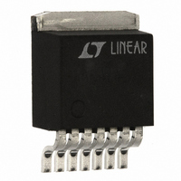
LT1513-2CR Linear Technology, LT1513-2CR Datasheet

LT1513-2CR
Specifications of LT1513-2CR
Available stocks
Related parts for LT1513-2CR
LT1513-2CR Summary of contents
Page 1
... The LT1513 can also drive a CCFL Royer converter with high efficiency in floating or grounded mode. Maximum switch current on the LT1513 is 3A. This allows battery charging currents for a single lithium-ion cell. Accuracy constant-voltage mode is perfect for lithium battery applications. Charging current can be easily programmed for all battery types ...
Page 2
... Operating Junction Temperature Range LT1513C ............................................... 125 C LT1513I ............................................ – 125 C Short Circuit ......................................... 150 C Storage Temperature Range ................ – 150 C Lead Temperature (Soldering, 10 sec)................. 300 ORDER PART NUMBER LT1513CR LT1513-2CR LT1513IR LT1513-2IR 7-LEAD TO-220 T = 125 C, JMAX and S/S pins open, unless otherwise noted. SW CONDITIONS Measured at FB Pin ...
Page 3
... IN 2.7V V 25V, V 0.6V S/S T < 2.7V V 25V S/S Note 2: The I FB Note 3: Consult factory for grade selected parts. Note 4: The I FB LT1513/LT1513-2 MIN TYP MAX 1.70 1.95 2.30 0.25 0.40 0.52 500 0.8 1 1.25 450 500 550 430 500 580 400 ...
Page 4
... BATTERY (A) (B) I CHRG (B) 8.4V BATTERY I CHRG (C) 4.2V BATTERY I CHRG (C) 0.2 0.4 0.6 0.8 1.0 1.2 1.4 1.6 1.8 2.0 CHARGING CURRENT (A) 1513 G07 REF – 100 125 150 TEMPERATURE ( C) LT1513 • G05 100 125 150 LT1513 • G03 = 0. 1.5A sn1513 1513fas ...
Page 5
... Keep the traces on this pin as short as possible to minimize radiation and voltage spikes. In particular, the path in Figure 1 which includes SW to C2, D1, C1 and around to the LT1513 ground pin should be as short as possible to minimize voltage spikes at switch turn-off. S/S (Pin 6): This pin can be used for shutdown and/or synchronization ...
Page 6
... REF *REMOVE ON LT1513-2 U OPERATION The LT1513 is a current mode switcher. This means that switch duty cycle is directly controlled by switch current rather than by output voltage or current. Referring to the Block Diagram, the switch is turned “on” at the start of each oscillator cycle turned “off” when switch current reaches a predetermined level ...
Page 7
... Maximum input voltage for the LT1513 is partly determined by battery voltage. A SEPIC converter has a maximum switch voltage equal to input voltage plus output voltage. The LT1513 has a maximum input voltage of 30V and a maximum switch voltage of 40V, so this limits maximum input voltage to 30V, or 40V – V ...
Page 8
... These capacitors do not have a turn-on surge limitation. The input capacitor must be connected directly to the V the ground plane close to the LT1513. Output Capacitor It is assumed as a worst case that all the switching output ripple current from the battery charger could flow in the output capacitor ...
Page 9
... Typical thermal resistance is 30 C/W for the R package but this number will C1,C3,C5 AND R3 TIED DIRECTLY TO GROUND PLANE Figure 4. LT1513 Suggested Partial Layout for Critical Thermal and Electrical Paths W U vary depending on the mounting technique (copper area, airflow, etc.). ...
Page 10
... R AND C MODEL PHASE DELAY IN THE MODULATOR P P THIS IS A SIMPLIFIED AC MODEL FOR THE LT1513 IN CONSTANT- VOLTAGE MODE. RESISTOR AND CAPACITOR NUMBERS CORRESPOND TO THOSE USED IN FIGURE 1. R THE PHASE DELAY IN THE MODULATOR 3pF FOR INDUCTOR. IT SHOULD BE SCALED PROPORTIONALLY FOR OTHER INDUCTOR VALUES (6pF FOR 20 H). THE MODULATOR IS A TRANSCONDUCTANCE WHOSE GAIN IS A FUNCTION OF INPUT AND BATTERY VOLTAGE AS SHOWN ...
Page 11
... V ). This is a very BAT Constant-Current Mode Loop Stability The LT1513 is normally very stable when operating in con also stant-current mode (see Figure 7), but there are certain con- BAT ditions which may create instabilities. The combination of higher value current sense resistors (low programmed charg- ...
Page 12
... Linear Technology Field Application Engineers have a CAD spreadsheet program for detailed calculations of circuit operating conditions. In addition, our Applications Depart- ment is always ready to lend a helping hand. The LT1371 data sheet may also be helpful. The LT1513 is identical except for the current amplifier circuitry. = 15V 0.4 (charging IN(MAX) ...
Page 13
... Figure 8 uses the LT1513-2 to provide switchable 1.35A and 0.13A constant-current modes. The circuit is based on a standard SEPIC battery charger circuit set to a single lithium-ion cell charge voltage of 4.1V. The LT1513-2 has I referenced to ground allowing a simple resistor network to set the charging current values. In constant-current mode, ...
Page 14
... To regulate bulb current in Figure 9, Royer input current is sensed with R2 and filtered with R3 and C6. This negative feedback signal is applied to the I LT1513. For more information on this circuit contact the LTC Applications Department and see Design Note 133. Consid- erable written application literature on Royer CCFL circuits is also available from other LTC Application and Design Notes ...
Page 15
... LT1513/LT1513-2 0.165 – 0.180 0.045 – 0.055 (4.191 – 4.572) (1.143 – 1.397) 15 TYP +0.008 0.004 –0.004 ...
Page 16
... LT1513/LT1513-2 RELATED PARTS PART NUMBER DESCRIPTION LT1239 Backup Battery Management System ® LTC 1325 Microprocessor Controlled Battery Management System LT1510 1.5A Constant-Current/Constant-Voltage Battery Charger LT1511 3.0A Constant-Current/Constant-Voltage Battery Charger with Input Current Limiting LT1512 SEPIC Constant-Current/Constant-Voltage Battery Charger Step-Up/Step-Down Charger for Current ...


