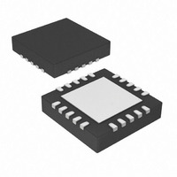
MCP73871-2CAI/ML Microchip Technology, MCP73871-2CAI/ML Datasheet - Page 20

MCP73871-2CAI/ML
Manufacturer Part Number
MCP73871-2CAI/ML
Description
IC USB/AC BATT CHRGR W/PPM 20QFN
Manufacturer
Microchip Technology
Specifications of MCP73871-2CAI/ML
Battery Type
Lithium-Ion (Li-Ion), Lithium-Polymer (Li-Pol)
Function
Charge Management
Voltage - Supply
4.4 V ~ 6 V
Operating Temperature
-40°C ~ 85°C
Mounting Type
Surface Mount
Package / Case
20-VFQFN Exposed Pad
Input Voltage
6V
Battery Charge Voltage
4.5V
Charge Current Max
1A
Battery Ic Case Style
QFN
No. Of Pins
20
No. Of Series Cells
1
Product
Charge Management
Output Voltage
4.2 V
Output Current
50 mA to 1000 mA
Operating Supply Voltage
4.5 V to 6 V
Maximum Operating Temperature
+ 85 C
Minimum Operating Temperature
- 40 C
Mounting Style
SMD/SMT
Lead Free Status / RoHS Status
Lead free / RoHS Compliant
For Use With
MCP73871DM-VPCC - DEMO BOARD FOR MCP73871MCP73871EV - EVALUATION BOARD FOR MCP73871
Lead Free Status / Rohs Status
Lead free / RoHS Compliant
Available stocks
Company
Part Number
Manufacturer
Quantity
Price
Company:
Part Number:
MCP73871-2CAI/ML
Manufacturer:
MICROCHIP
Quantity:
12 000
Part Number:
MCP73871-2CAI/ML
Manufacturer:
MICROCHIP/微芯
Quantity:
20 000
MCP73871
4.1
An internal undervoltage lockout (UVLO) circuit
monitors the input voltage and keeps the charger in
shutdown mode until the input supply rises above the
UVLO threshold.
In the event a battery is present when the input power
is applied, the input supply must rise approximately
100 mV above the battery voltage before the
MCP73871 device become operational.
The UVLO circuit places the device in shutdown mode
if the input supply falls to approximately 100 mV of the
battery voltage.
The UVLO circuit is always active. At any time, the
input supply is below the UVLO threshold or
approximately 100 mV of the voltage at the V
the MCP73871 device is placed in a shutdown mode.
During any UVLO condition, the battery reverse
discharge current shall be less than 2 µA.
4.2
The system load sharing feature gives the system
priority on input power, allowing the system to
power-up with deeply depleted battery packs.
With the SEL input active Low, the MCP73871 device
is designed to provide system power and Li-Ion battery
charging from a USB input while adhering to the current
limits governed by the USB specification.
With the SEL input active High, the MCP73871 device
limits the total supply current to 1.8A (system power
and charge current combined).
FIGURE 4-2:
Diagram.
4.3
For a charge cycle to begin, all UVLO conditions must
be met and a battery or output load must be present.
A charge current programming resistor must be
connected from PROG1 to V
When SEL = Low, PROG2 needs to tie to High or Low
for proper operation.
DS22090B-page 20
IN
UnderVoltage Lockout (UVLO)
System Load Sharing
Charge Qualification
System
Power
FET
Charge
FET
Current
Charge
Direction
Control
Direction
Control
Control
Limit
System Load Sharing
0.2Ω
0.2Ω
SS
when SEL = High.
Ideal
Diode,
Synchronous
Switch
BAT
OUT
V
BAT
pin,
4.4
If the voltage at the V
preconditioning threshold, the MCP73871 device
enters a preconditioning mode. The preconditioning
threshold is factory set. Refer to Section 1.0
“Electrical
threshold options.
In this mode, the MCP73871 device supplies 10% of
the fast charge current (established with the value of
the resistor connected to the PROG1 pin) to the
battery.
When the voltage at the V
preconditioning threshold, the MCP73871 device
enters the constant current (fast charge) mode.
4.5
During the constant current mode, the programmed
charge current is supplied to the battery or load. The
charge current is established using a single resistor
from PROG1 to V
charge current are calculated using the following
equation:
EQUATION 4-1:
Constant current mode is maintained until the voltage
at the V
When constant current mode is invoked, the internal
timer is reset.
4.5.1
If the internal timer expires before the recharge voltage
threshold is reached, a timer fault is indicated and the
charge cycle terminates. The MCP73871 device
remains in this condition until the battery is removed. If
the battery is removed, the MCP73871 device enters
the Stand-by mode where it remains until a battery is
reinserted.
4.6
When the voltage at the V
regulation voltage, V
begins. The regulation voltage is factory set to 4.10V
or 4.20V with a tolerance of ±0.5%.
Where:
R
PROG
I
REG
BAT
Preconditioning
Constant Current Mode - Fast
Charge
Constant Voltage Mode
pin reaches the regulation voltage, V
TIMER EXPIRED DURING
CONSTANT CURRENT - FAST
CHARGE MODE
Characteristics”
=
=
SS
I
kilo-ohms (kΩ)
milliampere (mA)
REG
REG
. The program resistor and the
© 2009 Microchip Technology Inc.
=
, constant voltage regulation
BAT
------------------- -
R
1000V
PROG1
BAT
pin is less than the
BAT
pin rises above the
for
pin reaches the
preconditioning
REG
.


