MCP73837T-NVI/MF Microchip Technology, MCP73837T-NVI/MF Datasheet - Page 19
MCP73837T-NVI/MF
Manufacturer Part Number
MCP73837T-NVI/MF
Description
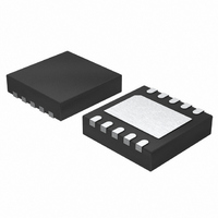
IC LIION CHRGR USB/AC-IN 10DFN
Manufacturer
Microchip Technology
Datasheet
1.MCP73838T-FJIMF.pdf
(30 pages)
Specifications of MCP73837T-NVI/MF
Battery Type
Lithium-Ion (Li-Ion), Lithium-Polymer (Li-Pol)
Operating Temperature
-40°C ~ 85°C
Function
Charge Management
Voltage - Supply
4.5 V ~ 6 V
Mounting Type
Surface Mount
Package / Case
10-DFN
Input Voltage
6V
Battery Charge Voltage
4.5V
Charge Current Max
1000mA
Battery Ic Case Style
DFN
No. Of Pins
10
No. Of Series Cells
1
Product
Charge Management
Output Voltage
4.2 V, 4.35 V, 4.4 V, 4.5 V
Output Current
1200 mA
Operating Supply Voltage
3.75 V to 6 V
Maximum Operating Temperature
+ 85 C
Minimum Operating Temperature
- 40 C
Mounting Style
SMD/SMT
Lead Free Status / RoHS Status
Lead free / RoHS Compliant
Lead Free Status / RoHS Status
Lead free / RoHS Compliant
Available stocks
Company
Part Number
Manufacturer
Quantity
Price
Company:

Part Number:
MCP73837T-NVI/MF
Manufacturer:
Microchip Technology
Quantity:
135


5.2.2
For the MCP73837/8, driving the PROG2 input to a
logic Low selects the low charge current setting
(maximum 100 mA). Driving the PROG2 input to a logic
High selects the high charge current setting (maximum
500 mA).
TABLE 5-1:
5.2.3
The power good (PG) option is a pseudo open-drain
output. The PG output can sink current, but not source
current. However, there is a diode path back to the
input, and as such, the output should be pulled up only
to the input. The PG output is low whenever the input
to the MCP73837 is above the UVLO threshold and
greater than the battery voltage. If the supply voltage is
above the UVLO, but below V
MCP73837 will pulse the PG output as the device
determines if a battery is present. The PG option is
available only on MCP73837.
© 2007 Microchip Technology Inc.
Shutdown
Standby
Preconditioning
Constant Current
Constant Voltage
Charge Complete - Standby
Temperature Fault
Timer Fault
System Test Mode
CHARGE CYCLE STATE
USB-PORT CURRENT
REGULATION SELECT (PROG2)
POWER GOOD (PG) OPTION
STATUS OUTPUTS
STAT1
Hi-Z
Hi-Z
Hi-Z
Hi-Z
Hi-Z
L
L
L
L
REG
(typical)+0.3V, the
STAT2
Hi-Z
Hi-Z
Hi-Z
Hi-Z
Hi-Z
Hi-Z
Hi-Z
L
L
Hi-Z
PG
L
L
L
L
L
L
L
L
5.2.4
The timer enable (TE) input option is used to enable or
disable the internal timer. A low signal on this pin
enables the internal timer and a high signal disables
the internal timer. The TE input can be used to disable
the timer when the charger is supplying current to
charge the battery and power the system load. The TE
input is compatible with 1.8V logic. The TE option is
available only on MCP73838.
5.2.5
The current regulation set input pin (PROG1/2) can be
used to terminate a charge at any time during the
charge cycle, as well as to initiate a charge cycle or to
initiate a recharge cycle. Placing a programming
resistor from the PROG1/2 input to V
device. Allowing the PROG1/2 input to float or applying
a logic-high input signal, disables the device and
terminates a charge cycle. When disabled, the device’s
supply current is reduced to 75 µA, typically.
TIMER ENABLE (TE) OPTION
DEVICE DISABLE (PROG1/2)
MCP73837/8
DS22071A-page 19
SS
enables the
Related parts for MCP73837T-NVI/MF
Image
Part Number
Description
Manufacturer
Datasheet
Request
R

Part Number:
Description:
IC,Battery Management,LLCC,10PIN,PLASTIC
Manufacturer:
Microchip Technology
Datasheet:

Part Number:
Description:
IC,Battery Management,TSSOP,10PIN,PLASTIC
Manufacturer:
Microchip Technology
Datasheet:
Part Number:
Description:
IC,Battery Management,TSSOP,10PIN,PLASTIC
Manufacturer:
Microchip Technology
Datasheet:
Part Number:
Description:
1A USB/DC Input Auto-swich Li-Ion Charger PG Output 10 DFN 3x3mm T/R
Manufacturer:
Microchip Technology
Datasheet:
Part Number:
Description:
1A USB/DC Input Auto-swich Li-Ion Charger PG Output 10 MSOP 3x3mm T/R
Manufacturer:
Microchip Technology
Datasheet:

Part Number:
Description:
SINGLE CELL Li-Ion/Li-POLYMER CHARGE MGMT CONTROLLER, -40C to +85C, 14-SOIC 150mil, T/R
Manufacturer:
Microchip Technology
Datasheet:

Part Number:
Description:
Manufacturer:
Microchip Technology Inc.
Datasheet:
Part Number:
Description:
Manufacturer:
Microchip Technology Inc.
Datasheet:
Part Number:
Description:
Manufacturer:
Microchip Technology Inc.
Datasheet:
Part Number:
Description:
Manufacturer:
Microchip Technology Inc.
Datasheet:
Part Number:
Description:
Manufacturer:
Microchip Technology Inc.
Datasheet:
Part Number:
Description:
Manufacturer:
Microchip Technology Inc.
Datasheet: