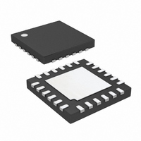
LTC4007EUFD-1#TRPBF Linear Technology, LTC4007EUFD-1#TRPBF Datasheet - Page 18

LTC4007EUFD-1#TRPBF
Manufacturer Part Number
LTC4007EUFD-1#TRPBF
Description
IC CHARGER BATTERY 4A 24-QFN
Manufacturer
Linear Technology
Type
Battery Chargerr
Datasheet
1.LTC4007EUFD-1PBF.pdf
(24 pages)
Specifications of LTC4007EUFD-1#TRPBF
Function
Charge Management
Battery Type
Lithium-Ion (Li-Ion)
Voltage - Supply
6 V ~ 28 V
Operating Temperature
-40°C ~ 85°C
Mounting Type
Surface Mount
Package / Case
24-WFQFN Exposed Pad
Output Current
4A
Output Voltage
4.1/4.2V
Operating Supply Voltage (min)
6V
Operating Supply Voltage (max)
28V
Operating Temp Range
-40C to 85C
Package Type
QFN
Mounting
Surface Mount
Pin Count
24
Operating Temperature Classification
Industrial
Lead Free Status / RoHS Status
Lead free / RoHS Compliant
Available stocks
Company
Part Number
Manufacturer
Quantity
Price
APPLICATIO S I FOR ATIO
LTC4007-1
Adapter Limiting
An important feature of the LTC4007-1 is the ability to
automatically adjust charging current to a level which
avoids overloading the wall adapter. This allows the prod-
uct to operate at the same time that batteries are being
charged without complex load management algorithms.
Additionally, batteries will automatically be charged at the
maximum possible rate of which the adapter is capable.
This feature is created by sensing total adapter output
current and adjusting charging current downward if a
preset adapter current limit is exceeded. True analog
control is used, with closed-loop feedback ensuring that
adapter load current remains within limits. Amplifier CL1
in Figure 8 senses the voltage across R
between the CLP and CLN pins. When this voltage exceeds
100mV, the amplifier will override programmed charging
current to limit adapter current to 100mV/R
filter formed by 5kΩ and 15nF is required to eliminate
switching noise. If the current limit is not used, CLP should
be connected to CLN.
Note that the I
across R
threshold.
Setting Input Current Limit
To set the input current limit, you need to know the
minimum wall adapter current rating. Subtract 7% for the
18
*R
LTC4007-1
CL
=
ADAPTER CURRENT LIMIT
CL
CL1
is 93mV, before the adapter limit regulation
100mV
Figure 8. Adapter Current Limiting
+
–
CL
100mV
pin will be asserted when the voltage
U
+
15
16
U
CLP
CLN
+
15nF
C
W
IN
R
CL
*
5k
CL
CL
, connected
. A lowpass
AC ADAPTER
U
INPUT
40071 F08
V
IN
input current limit tolerance and use that current to deter-
mine the resistor value.
Table 5. Common R
* Values shown above are rounded to nearest standard value.
As is often the case, the wall adapter will usually have at
least a +10% current limit margin and many times one can
simply set the adapter current limit value to the actual
adapter rating (see Table 5).
Designing the Thermistor Network
There are several networks that will yield the desired
function of voltage vs temperature needed for proper
operation of the thermistor. The simplest of these is the
voltage divider shown in Figure 9. Unfortunately, since the
HIGH/LOW comparator thresholds are fixed internally,
there is only one thermistor type that can be used in this
network; the thermistor must have a HIGH/LOW resis-
tance ratio of 1:7. If this happy circumstance is true for
you, then simply set R9 = R
RATING (A)
ADAPTER
R
I
LIM
CL
1.5
1.8
2.3
2.5
2.7
2
3
= 100mV/I
= Adapter Min Current –
(Adapter Min Current • 7%)
Figure 9. Voltage Divider Thermistor Network
R CL VALUE*
LTC4007-1
(Ω) 1%
0.045
0.039
0.036
0.033
0.06
0.05
0.03
CL
LIM
NTC
Resistor Values
7
R9
DISSIPATION (W)
TH(LOW)
R CL POWER
0.135
0.162
0.206
0.225
0.241
0.18
0.27
C7
.
40071
R
TH
F09
R CL POWER
RATING (W)
0.25
0.25
0.25
0.25
0.5
0.5
0.5
40071f


