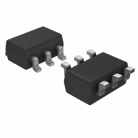
S-8261ABSMD-G3ST2G Seiko Instruments, S-8261ABSMD-G3ST2G Datasheet - Page 9

S-8261ABSMD-G3ST2G
Manufacturer Part Number
S-8261ABSMD-G3ST2G
Description
IC LI-ION BATT PROTECT SOT23-6
Manufacturer
Seiko Instruments
Datasheet
1.S-8261AAJMD-G2JT2G.pdf
(33 pages)
Specifications of S-8261ABSMD-G3ST2G
Function
Over/Under Voltage Protection
Battery Type
Lithium-Ion (Li-Ion), Lithium-Polymer (Li-Pol)
Operating Temperature
-40°C ~ 85°C
Mounting Type
Surface Mount
Package / Case
SOT-23-6
Output Voltage
4.28 V
Operating Supply Voltage
1.5 V to 28 V
Maximum Operating Temperature
+ 85 C
Minimum Operating Temperature
- 40 C
Mounting Style
SMD/SMT
Lead Free Status / RoHS Status
Lead free / RoHS Compliant
*1. Since products are not screened at high and low temperatures, the specification for this temperature range is
DETECTION VOLTAGE
Overcharge detection voltage
V
Overcharge hysteresis voltage
V
Overdischarge detection voltage
V
Overdischarge hysteresis voltage
V
Overcurrent 1 detection voltage
V
Overcurrent 2 detection voltage
Load short-circuiting detection voltage
Charger detection voltage
INPUT VOLTAGE, OPERATION VOLTAGE
Operation voltage between VDD and VSS
Operation voltage between VDD and VM
CURRENT CONSUMPTION (with power-down function)
Current consumption in normal operation
Current consumption at power down
CURRENT CONSUMPTION (without power-down function)
Current consumption in normal operation
Overdischarge current consumption
OUTPUT RESISTANCE
CO pin resistance “H”
CO pin resistance “L”
DO pin resistance “H”
DO pin resistance “L”
VM INTERNAL RESISTANCE
Internal resistance between VM and VDD
Internal resistance between VM and VSS
0 V BATTERY CHARGING FUNCTION
0 V battery charge starting charger voltage
0 V battery charge inhibition battery voltage V
Rev.5.0
CU
HC
DL
HD
IOV1
2. Except Detection Delay Time (−40°C to +85°C
= 2.0 V to 3.0 V, 10 mV Step
= 3.9 V to 4.4 V, 5 mV Step
= 0.1 V to 0.4 V, 50 mV Step
= 0.0 V to 0.7 V, 100 mV Step
guaranteed by design, not
= 0.05 V to 0.3 V, 10 mV Step
_00
Item
tested in production.
Symbol
V
V
V
V
V
V
V
V
V
V
I
I
I
I
R
R
R
R
R
R
V
OPE
PDN
OPE
OPED
CU
HC
DL
HD
IOV1
IOV2
SHORT
CHA
DSOP1
DSOP2
0CHA
0INH
COH
COL
DOH
DOL
VMD
VMS
Internal circuit operating voltage
Internal circuit operating voltage
V
V
V
V
V
V
V
V
V
V
0 V battery charging available
0 V battery charging unavailable
DD
DD
DD
DD
CO
CO
DO
DO
DD
DD
= 3.5 V, V
= V
= 3.5 V, V
= V
= 1.8 V, V
= 3.5 V, V
= 3.0 V, V
= 0.5 V, V
= 3.0 V, V
= 0.5 V, V
Seiko Instruments Inc.
VM
VM
= 1.5 V
= 1.5 V
LOW DROPOUT CMOS VOLTAGE REGULATOR
Condition
VM
VM
VM
VM
DD
DD
DD
DD
Table 7
⎯
⎯
⎯
⎯
⎯
⎯
⎯
⎯
= 0 V
= 0 V
= 3.5 V, V
= 4.5 V, V
= 3.5 V, V
= V
= 0 V
= 1.0 V
*1
)
VM
= 1.8 V
VM
VM
VM
= 0 V
= 0 V
= 0 V
(Ta = −40°C to +85°C
−0.055
−0.025
−0.080
−0.050
−0.021
V
0.37
−1.2
V
V
V
Min.
V
0.7
1.5
1.5
0.7
0.7
0.7
1.2
1.2
1.2
1.2
7.2
1.7
78
⎯
⎯
IOV1
CU
HC
DL
HD
V
−0.7
V
V
V
300
Typ.
V
0.5
1.2
3.5
3.5
3.0
20
⎯
⎯
⎯
⎯
⎯
IOV1
5
5
5
5
CU
HC
HD
DL
+0.040
+0.025
+0.080
+0.050
+0.021
1310
V
0.63
−0.2
*1
Max.
V
V
V
V
1.7
8.0
0.1
8.0
6.0
0.3
28
15
15
15
15
44
⎯
IOV1
8
CU
HC
HD
DL
unless otherwise specified)
S-8261 Series
Unit
μA
μA
μA
μA
kΩ
kΩ
kΩ
kΩ
kΩ
kΩ
V
V
V
V
V
V
V
V
V
V
V
V
Condition
Test
11
12
⎯
⎯
1
1
2
2
3
3
3
4
5
5
5
5
7
7
8
8
6
6
Circuit
Test
⎯
⎯
1
1
2
2
2
2
2
2
2
2
2
2
4
4
4
4
3
3
2
2
9


