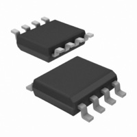
IR2520DSTRPBF International Rectifier, IR2520DSTRPBF Datasheet

IR2520DSTRPBF
Specifications of IR2520DSTRPBF
Available stocks
Related parts for IR2520DSTRPBF
IR2520DSTRPBF Summary of contents
Page 1
Features 600V Half Bridge Driver Integrated Bootstrap FET Adaptive zero-voltage switching (ZVS) Internal Crest Factor Over-Current Protection 0 to 6VDC Voltage Controlled Oscillator Programmable minimum frequency Micropower Startup Current (80uA) Internal 15.6V zener clamp on Vcc Small DIP8/SO8 Package Also ...
Page 2
IR2520D(S)& (PbF) Absolute Maximum Ratings Absolute maximum ratings indicate sustained limits beyond which damage to the device may occur. All voltage param- eters are absolute voltages referenced to COM, all currents are defined positive into any lead. The thermal resistance ...
Page 3
Electrical Characteristics 14V +/- 0.25V BIAS LO Symbol Definition Supply Characteristics V V and V supply undervoltage positive going CCUV threshold V V and V supply undervoltage negative going ...
Page 4
IR2520D(S)& (PbF) Electrical Characteristics 14V +/- 0.25V BIAS LO Symbol Definition Protection Characteristics V VCO voltage when entering run mode VCO_RUN CSCF Crest factor peak-to-average fault factor VS_ Maximum crest factor ...
Page 5
Block Diagram VCC 1 15.6V COM 2 I FMAX I FMIN I I VCO QS VCO 4 5. Fault 0.8V Logic VCC S Q UVLO 4. FMIN R RFMIN FMIN 3 ...
Page 6
IR2520D(S)& (PbF) State Diagram VCC < 10V (VCCUV-) FAULT Mode 1 / -Bridge Off VCO ≅ µA I 100 QCCFLT FMIN Crest Factor > 5.0 (CSCF < 0.82V VCO (V ) ...
Page 7
Functional Description Under-voltage Lock-Out Mode The under-voltage lock-out mode (UVLO) is defined as the state the IR2520D is in when VCC is below the turn-on threshold of the IC. The IR2520D UVLO is designed to main- tain an ultra-low supply ...
Page 8
IR2520D(S)& (PbF) V VCO 6V 4.8V 0.85V Frequency Sweep Mode Freq fmax fmin Fig. 3 IR2520D Frequency sweep mode timing diagram. High -Q Vout Ignition Vin Run Low -Q fmin Fig. 4 Resonant tank Bode plot with lamp operating points. ...
Page 9
DC bus during a mains brown-out or mains interrupt, lamp variations over time, or component variations. To protect against this, an internal high-voltage MOSFET is turned on at the turn-off of HO and the ...
Page 10
IR2520D(S)& (PbF) over-current fault. By using the RDSon of the external low- side MOSFET for current sensing and the VS-sensing circuitry, the IR2520D eliminates the need for an additional current sensing resistor, filter and current-sensing pin. To cancel changes in ...
Page 11
VCCUV VCCUV - Temperature(°C) Fig. 9 VCCUV+/- vs TEMP 12 10 VBSUV+ 8 VBSUV Temperature(°C) Fig. 11 VBSUV+/- vs TEMP www.irf.com IR2520D(S) ...
Page 12
IR2520D(S)& (PbF VVCO= VVCO= Temperature(C) Fig. 13 Frequency vs TEMP REMIN=82K ...
Page 13
TDHO 2 TDLO Temperature(°C) Fig. 17 DTHO, DTLO vs TEMP VCO= Temperature(C) Fig. 19 ...
Page 14
IR2520D(S)& (PbF Temperature(°C) Fig. 21 CSCF vs TEMP VS_OFFSET=0. Temperature(C) ( Fig. 23 VFMIN vs TEMP ...
Page 15
Temperature(°C) Fig. 26 IBS2 vs TEMP IR2520D(S) & (PbF ...
Page 16
IR2520D(S)& (PbF) Case outlines 0.25 [.010 0.25 [.010 NOTES: 1. DIMENSIONING & TOLERANCING PER ASME Y14.5M-1994. ...
Page 17
LEADFREE PART MARKING INFORMATION Part number Date code Pin 1 Identifier ? MARKING CODE P Lead Free Released Non-Lead Free Released Basic Part (Non-Lead Free) 8-Lead PDIP IR2520D order IR2520D 8-Lead SOIC IR2520DS order IR2520DS IR WORLD HEADQUARTERS: 233 Kansas ...


