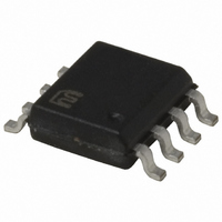
MIC4100YM Micrel Inc, MIC4100YM Datasheet

MIC4100YM
Specifications of MIC4100YM
Available stocks
Related parts for MIC4100YM
MIC4100YM Summary of contents
Page 1
... Typical Application 9V to 16V Bias Controller Micrel Inc. • 2180 Fortune Drive • San Jose, CA 95131 • USA • tel +1 (408) 944-0800 • fax + 1 (408) 474-1000 • http://www.micrel.com March 2006 Features • Bootstrap supply max voltage to 118V DC • Supply voltage up to 16V • ...
Page 2
... Micrel, Inc. Ordering Information Part Number Standard Pb-Free MIC4100BM MIC4100YM MIC4101BM MIC4101YM Pin Configuration Pin Description Pin Number Pin Name 1 VDD VSS 8 LO March 2006 Input Junction Temp. Range CMOS TTL VDD SOIC-8L (M) Pin Function Positive Supply to lower gate drivers. Decouple this pin to VSS (Pin 7). Bootstrap diode connected to HB (pin 2) ...
Page 3
Micrel, Inc. Absolute Maximum Ratings Supply Voltage ( – ...................... -0.3V to 18V Input Voltages ( ......................... -0. LI, HI Voltage .............................. -0. ...
Page 4
Micrel, Inc. Parameter Symbol Under Voltage Protection V Rising Threshold Threshold Hysteresis Rising Threshold V HB Threshold Hysteresis V Bootstrap Diode Low-Current Forward Voltage V High-Current Forward Voltage V Dynamic Resistance R LO Gate ...
Page 5
Micrel, Inc. Parameter Switching Specifications Lower Turn-Off Propagation Delay (LI Falling to LO Falling) Upper Turn-Off Propagation Delay (HI Falling to HO Falling) Lower Turn-On Propagation Delay (LI Rising to LO Rising) Upper Turn-On Propagation Delay (HI Rising to HO ...
Page 6
Micrel, Inc. Timing Diagrams HI HPLH t LPLH HO,LO Note: All propagation delays are measured from the 50% voltage level. March 2006 t HPLH t LO LPLH MON MOFF MIC4100/1 M9999-031506 ...
Page 7
Micrel, Inc. Typical Characteristics March 2006 7 MIC4100/1 M9999-031506 ...
Page 8
Micrel, Inc. Typical Characteristics (cont.) March 2006 8 MIC4100/1 M9999-031506 ...
Page 9
Micrel, Inc. Functional Diagram March 2006 LEVE L UVLO SHIFT UVLO Figure 1. MIC4100 Functional Block Diagram DRIVER HS LO DRIVER MIC4100/1 M9999-031506 ...
Page 10
Micrel, Inc. Functional Description The MIC4100 is a high voltage, non-inverting, dual MOSFET driver that is designed to independently drive both high-side and low-side N-Channel MOSFETs. The block diagram of the MIC4100 is shown in Figure 1. Both drivers contain ...
Page 11
Micrel, Inc. Vdd LO Vss Figure 3 High-Side Driver and Bootstrap Circuit A block diagram of the high-side driver and bootstrap circuit is shown in Figure 4. This driver is designed to drive a floating N-channel MOSFET, whose source terminal ...
Page 12
Micrel, Inc. Application Information Power Dissipation Considerations Power dissipation in the driver can be separated into three areas: • Internal diode dissipation in the bootstrap circuit • Internal driver dissipation • Quiescent current dissipation used to supply the internal logic ...
Page 13
Micrel, Inc. external diode HB Vdd Level HO HI shift HS LI Vss Figure 6 Gate Driver Power Dissipation Power dissipation in the output driver stage is mainly caused by charging and discharging the gate to source and gate to ...
Page 14
Micrel, Inc. = × dirver gs and = × × driver gs where E is the energy dissipated per switching driver P is the power dissipated by switching driver Qg is the total ...
Page 15
Micrel, Inc. capacitors are recommended for most applications. The minimum capacitance value should be increased if low voltage capacitors are use since even good quality dielectric capacitors, such as X5R, will lose 40% to 70% of their capacitance value at ...
Page 16
Micrel, Inc. Vdd C Vdd High-side drive turn-on current path Turn-Off Current Paths Figure 10 The following circuit guidelines should be adhered to for optimum circuit performance: 1. The Vcc and HB bypass capacitors must ...
Page 17
Micrel, Inc. The circuit is configured as a synchronous buck power stage. The high-side MOSFET drain connects to the input supply voltage (drain) and the source connects to the switching node. The low-side MOSFET drain connects to the switching node ...
Page 18
Micrel, Inc. Package Information MICREL, INC. 2180 FORTUNE DRIVE SAN JOSE, CA 95131 USA TEL +1 (408) 944-0800 FAX +1 (408) 474-1000 WEB http:/www.micrel.com The information furnished by Micrel in this data sheet is believed to be accurate and reliable. ...


