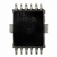
BTS5242-2L Infineon Technologies, BTS5242-2L Datasheet - Page 20

BTS5242-2L
Manufacturer Part Number
BTS5242-2L
Description
IC PWR SWITCH HISIDE PG-DSO-12-9
Manufacturer
Infineon Technologies
Series
PROFET®r
Type
High Sider
Specifications of BTS5242-2L
Package / Case
DSO-12
Input Type
Non-Inverting
Number Of Outputs
2
On-state Resistance
19 mOhm
Current - Output / Channel
6A
Current - Peak Output
50A
Voltage - Supply
4.5 V ~ 28 V
Operating Temperature
-40°C ~ 150°C
Mounting Type
Surface Mount
On Resistance (max)
0.019 Ohms
Maximum Operating Temperature
+ 150 C
Minimum Operating Temperature
- 40 C
Maximum Power Dissipation
1400 mW
Mounting Style
SMD/SMT
Supply Current
3.2 mA
Power Load Switch Type
High Side
Input Voltage
28V
Current Limit
40A
On State Resistance
0.019ohm
Thermal Protection
ESD
Power Dissipation Pd
1.4W
No. Of Outputs
2
Internal Switch
No
Rohs Compliant
Yes
Distribution Switch Case Style
SOIC
Lead Free Status / RoHS Status
Lead free / RoHS Compliant
Lead Free Status / RoHS Status
Lead free / RoHS Compliant, Lead free / RoHS Compliant
Other names
BTS5242-2LINTR
BTS52422LXT
SP000281082
BTS52422LXT
SP000281082
Available stocks
Company
Part Number
Manufacturer
Quantity
Price
Company:
Part Number:
BTS5242-2L
Manufacturer:
IT
Quantity:
12 000
Part Number:
BTS5242-2L
Manufacturer:
INFINEON/英飞凌
Quantity:
20 000
Figure 16
7.2
Details about timings between the diagnosis signal I
state can be found in
Figure 17
For open load diagnosis in off-state an external output pull-up resistor ( R
pull-up resistor, the leakage currents and the open load threshold voltage V
Depending on the application, an additional pull down resistor at the output might be necessary.
I
humidity.
To reduce the stand-by current of the system, an open load resistor switch ( S
current of the BTS5242-2L is minimized, when both input pins (IN1 and IN2) are on low level or left open and
V
current through the sense resistor, which causes an increase in supply current. To reduce the stand-by current to
a minimum, the open load condition needs to be suppressed.
The resistors
polarity and over voltage.
Data Sheet
leakage
OUT
<
defines the leakage current in the complete system including I
V
OUT(OL)
V
bb(min)
Timing of Diagnosis Signal in Over Load Condition
OFF-State Diagnosis
Timing of Diagnosis Signal in OFF-state
R
. In case of open load in off state (
lim
is the minimum supply voltage at which the open load diagnosis in off-state must be ensured.
are recommended to limit the current through the sense pins IS1 and IS2 in case of reverse
V
I
T
OUT
I
IS
L
IN
I
j
IS
Figure
ON
t
Open Load, pull-up resistor active
sIS(LC)
17.
over load (current limitation & thermal toggling)
t
d(fault)
V
IS(fault)
/ R
S
V
IS(fault)
R
OL
/ R
S
=
OFF
V
V
---------------------------------------------------------- -
bb(min)
OUT
IS
and the output voltage V
>
20
I
–
V
leakage
V
OUT(OL)
pull-up resistor
OUT(OL,max)
inactive
normal operation
and
V
t
hIS(OTR)
IN
t
s(fault)
L(OL)
Smart High-Side Power Switch
= 0 V), the fault voltage V
OL
T
j(SC)
) is recommended. For calculation of
and external leakages e.g. due to
OL
OUT
OUT(OL)
) is recommended. The stand-by
and the load current I
OverTemp .emf
has to be taken into account.
SwitchOff.emf
t
t
t
t
t
t
Rev.1.2, 2008-09-01
BTS5242-2L
IS(fault)
Diagnosis
L
drives a
in OFF-


