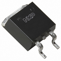
BUK116-50L,118 NXP Semiconductors, BUK116-50L,118 Datasheet - Page 5

BUK116-50L,118
Manufacturer Part Number
BUK116-50L,118
Description
TOPFET LOGIC LVL 50V D2PAK
Manufacturer
NXP Semiconductors
Series
TOPFET™r
Type
Low Sider
Datasheet
1.BUK116-50L118.pdf
(13 pages)
Specifications of BUK116-50L,118
Input Type
Non-Inverting
Number Of Outputs
1
On-state Resistance
22 mOhm
Current - Output / Channel
50A
Current - Peak Output
200A
Mounting Type
Surface Mount
Package / Case
D²Pak, TO-263 (4 leads + tab)
Lead Free Status / RoHS Status
Lead free / RoHS Compliant
Voltage - Supply
-
Operating Temperature
-
Other names
934044320118
BUK116-50L /T3
BUK116-50L /T3
BUK116-50L /T3
BUK116-50L /T3
Philips Semiconductors
INPUT CHARACTERISTICS
T
SWITCHING CHARACTERISTICS
T
CAPACITANCES
T
1 The resistance of the internal transistor which discharges the power MOSFET gate capacitance when overload protection operates.
2 Applications using a lower value for R
3 For applications requiring a lower value for R
July 1996
Logic level TOPFET
SMD version of BUK106-50L/S
mb
SYMBOL PARAMETER
V
I
V
R
R
R
mb
SYMBOL PARAMETER
t
t
t
t
mb
SYMBOL PARAMETER
C
C
C
C
C
IS
d on
r
d off
f
IS(TO)
(CL)IS
ISL
IS
I
iss
oss
rss
pso
fso
= 25 ˚C unless otherwise specified
= 25 ˚C; R
= 25 ˚C; f = 1 MHz
The external drive circuit should be such that the input voltage does not exceed V
operated. Refer also to figure for latched input characteristics.
switch off the input.
Normal operation
Input threshold voltage
Input current
Input clamp voltage
Overload protection latched
Input resistance
Application information
External input resistances for
internal overvoltage clamping
internal overload protection
Turn-on delay time
Rise time
Turn-off delay time
Fall time
Input capacitance
Output capacitance
Reverse transfer capacitance
Protection supply pin
capacitance
Flag pin capacitance
I
= 50 ; R
IS
= 50
1
IS
would require external overvoltage protection.
(see figure 29); resistive load R
I
, an external overload protection strategy is possible using the flag pin to ‘tell’ the control circuit to
3
2
CONDITIONS
V
V
I
V
V
(see figure 29)
R
R
CONDITIONS
V
V
CONDITIONS
V
V
V
V
V
I
DS
IS
PS
PS
DD
DD
DS
DS
DS
PS
FS
= 1 mA
I
IS
=
= 10 V
=
= 10 V; V
= 5 V; I
= 5 V
= 10 V
= 25 V; V
= 25 V; V
= 25 V; V
= 10 V
= 15 V; V
= 15 V; V
;
;
5
D
= 1 mA
PS
IS
IS
IS
IS
IS
: 0 V
: 10 V
= 0 V
= 0 V
= 0 V
= 0 V
T
I
T
I
T
V
V
V
mb
I
I
L
mb
mb
DS
II
II
= 5 mA;
= 5 mA;
= 10 . For waveforms see figure 28.
= 5 V
= 10 V
= 150 ˚C
= 150 ˚C
= 150 ˚C
> 30 V
10 V
0 V
IS(TO)
minimum when the overload protection has
MIN.
MIN.
MIN.
100
1.0
0.5
11
1
2
-
-
-
-
-
-
-
-
-
-
-
-
-
-
TYP.
TYP.
TYP.
1250
280
120
650
150
1.5
BUK116-50L/S
10
13
55
95
35
60
10
35
30
20
-
-
-
-
Product specification
MAX.
MAX.
MAX.
1800
1000
100
250
2.0
-
-
-
-
-
-
-
-
-
-
-
-
-
-
-
Rev 1.000
UNIT
UNIT
UNIT
nA
k
k
pF
pF
pF
pF
pF
ns
ns
ns
ns
V
V
V


