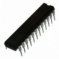
L6228N STMicroelectronics, L6228N Datasheet - Page 12

L6228N
Manufacturer Part Number
L6228N
Description
IC DRIVER STEPPER MOTOR 24PWRDIP
Manufacturer
STMicroelectronics
Type
Driverr
Datasheet
1.L6228DTR.pdf
(26 pages)
Specifications of L6228N
Applications
Stepper Motor Driver
Number Of Outputs
1
Current - Output
1.4A
Voltage - Supply
8 V ~ 52 V
Operating Temperature
-25°C ~ 125°C
Mounting Type
Through Hole
Package / Case
24-DIP (0.300", 7.62mm)
Product
Stepper Motor Controllers / Drivers
Operating Supply Voltage
8 V to 52 V
Supply Current
1.4 A
Mounting Style
Through Hole
Motor Type
Stepper
No. Of Outputs
4
Output Current
3.55A
Output Voltage
52V
Supply Voltage Range
8V To 52V
Driver Case Style
DIP
No. Of Pins
24
Operating Temperature Range
-40°C To +150°C
Rohs Compliant
Yes
For Use With
497-6818 - EVAL BOARD FOR L6228Q
Lead Free Status / RoHS Status
Lead free / RoHS Compliant
Voltage - Load
-
Lead Free Status / Rohs Status
Lead free / RoHS Compliant
Other names
497-5350-5
L6228N
L6228N
Available stocks
Company
Part Number
Manufacturer
Quantity
Price
Company:
Part Number:
L6228N
Manufacturer:
STMicroelectronics
Quantity:
740
Part Number:
L6228N
Manufacturer:
ST
Quantity:
20 000
L6228
Figure 11. Output Current Regulation Waveforms
Figure 12 shows the magnitude of the Off Time t
calculated from the equations:
where R
Therefore:
These values allow a sufficient range of t
The capacitor value chosen for C
Rise Time t
monostable is triggered. Therefore, the on time t
be bigger than t
can not be smaller than the minimum on time t
12/26
R
V
V
SENSE
I
SENSE
t
t
20K
0.47nF
t
t
t
OUT
RCFALL
OFF
DT
OFF(MIN)
OFF(MAX)
V
REF
2.5V
OFF
V
ON
5V
REF
OFF
0
RC
= 1µs (typical value)
= t
RCRISE
and C
RCFALL
SYNCHRONOUS OR QUASI
SYNCHRONOUS RECTIFICATION
= 0.6 · R
R
D01IN1334
= 6.6µs
C
RCRISE
OFF
= 6ms
OFF
OFF
will only be an issue if the capacitor is not completely charged before the next time the
+ t
100K
OFF
are the external component values and t
for allowing a good current regulation by the PWM stage. Furthermore, the on time t
100nF
DT
= 0.6 · R
· C
OFF
OFF
OFF
also affects the Rise Time t
· C
OFF
OFF
B
to implement the drive circuit for most motors.
Slow Decay
ON(MIN)
+ t
t
ON
RCFALL
DT
OFF
1 s t
1 s t
t
t
RCRISE
, which depends by motors and supply parameters, has to
OFF
C
.
versus C
BLANK
DT
D
OFF
DT
RCRISE
is the internally generated Dead Time with:
t
ON
A
and R
of the voltage at the pin RCOFF. The
B
OFF
Slow Decay
values. It can be approximately
t
RCFALL
1 s t
1 s t
t
t
RCRISE
OFF
C
BLANK
DT
D
ON


