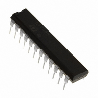
L6208N STMicroelectronics, L6208N Datasheet - Page 10

L6208N
Manufacturer Part Number
L6208N
Description
IC DRIVER STEPPER MOTOR 24PWRDIP
Manufacturer
STMicroelectronics
Type
Driverr
Datasheet
1.L6208D013TR.pdf
(27 pages)
Specifications of L6208N
Applications
Stepper Motor Driver, 2 Phase
Number Of Outputs
2
Current - Output
5.6A
Voltage - Supply
8 V ~ 52 V
Operating Temperature
-25°C ~ 125°C
Mounting Type
Through Hole
Package / Case
24-DIP (0.300", 7.62mm)
Operating Supply Voltage
8 V to 52 V
Supply Current
0.01 A
Mounting Style
Through Hole
Motor Type
Stepper
No. Of Outputs
4
Output Current
7.1A
Output Voltage
52V
Supply Voltage Range
8V To 52V
Driver Case Style
DIP
No. Of Pins
24
Rohs Compliant
Yes
For Use With
497-5488 - EVAL BOARD FOR L6208N DIP497-4136 - EVAL BOARD FOR L6208 SERIES
Lead Free Status / RoHS Status
Lead free / RoHS Compliant
Voltage - Load
-
Lead Free Status / Rohs Status
Lead free / RoHS Compliant
Other names
497-5342-5
L6208N
L6208N
Available stocks
Company
Part Number
Manufacturer
Quantity
Price
Company:
Part Number:
L6208N
Manufacturer:
STMicroelectronics
Quantity:
226
Company:
Part Number:
L6208N
Manufacturer:
POWEREX
Quantity:
1 000
Part Number:
L6208N
Manufacturer:
ST
Quantity:
20 000
L6208
Figure 6. Charge Pump Circuit
LOGIC INPUTS
Pins CONTROL, HALF/FULL, CLOCK, RESET and CW/CCW are TTL/CMOS and uC compatible logic inputs.
The internal structure is shown in Fig. 7. Typical value for turn-on and turn-off thresholds are respectively
V
Pin EN (Enable) has identical input structure with the exception that the drain of the Overcurrent and thermal
protection MOSFET is also connected to this pin. Due to this connection some care needs to be taken in driving
this pin. The EN input may be driven in one of two configurations as shown in Fig. 8 or 9. If driven by an open
drain (collector) structure, a pull-up resistor R
driver is a standard Push-Pull structure the resistor R
9. The resistor R
C
Protection section.
Figure 7. Logic Inputs Internal Structure
Figure 8. EN Pin Open Collector Driving
Figure 9. EN Pin Push-Pull Driving
10/27
th(ON)
EN
are respectively 100K
= 1.8V and V
EN
th(OFF)
should be chosen in the range from 2.2K
= 1.3V.
and 5.6nF. More information on selecting the values is found in the Overcurrent
PUSH-PULL
OUTPUT
COLLECTOR
OUTPUT
OPEN
VCP
R
EN
D1
R
C
5V
P
P
D2
PROTECTION
R
EN
EN
C
VBOOT
EN
EN
C
EN
EN
ESD
and a capacitor C
C
PROTECTION
BOOT
PROTECTION
EN
ESD
ESD
VS
and the capacitor C
A
5V
VS
D01IN1329
B
to 180K . Recommended values for R
D01IN1328
EN
5V
are connected as shown in Fig. 8. If the
V
5V
S
D01IN1330
D01IN1331
EN
are connected as shown in Fig.
EN
and


