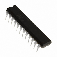
L6208N STMicroelectronics, L6208N Datasheet - Page 6

L6208N
Manufacturer Part Number
L6208N
Description
IC DRIVER STEPPER MOTOR 24PWRDIP
Manufacturer
STMicroelectronics
Type
Driverr
Datasheet
1.L6208D013TR.pdf
(27 pages)
Specifications of L6208N
Applications
Stepper Motor Driver, 2 Phase
Number Of Outputs
2
Current - Output
5.6A
Voltage - Supply
8 V ~ 52 V
Operating Temperature
-25°C ~ 125°C
Mounting Type
Through Hole
Package / Case
24-DIP (0.300", 7.62mm)
Operating Supply Voltage
8 V to 52 V
Supply Current
0.01 A
Mounting Style
Through Hole
Motor Type
Stepper
No. Of Outputs
4
Output Current
7.1A
Output Voltage
52V
Supply Voltage Range
8V To 52V
Driver Case Style
DIP
No. Of Pins
24
Rohs Compliant
Yes
For Use With
497-5488 - EVAL BOARD FOR L6208N DIP497-4136 - EVAL BOARD FOR L6208 SERIES
Lead Free Status / RoHS Status
Lead free / RoHS Compliant
Voltage - Load
-
Lead Free Status / Rohs Status
Lead free / RoHS Compliant
Other names
497-5342-5
L6208N
L6208N
Available stocks
Company
Part Number
Manufacturer
Quantity
Price
Company:
Part Number:
L6208N
Manufacturer:
STMicroelectronics
Quantity:
226
Company:
Part Number:
L6208N
Manufacturer:
POWEREX
Quantity:
1 000
Part Number:
L6208N
Manufacturer:
ST
Quantity:
20 000
L6208
ELECTRICAL CHARACTERISTICS (continued)
(T
6/27
Switching Characteristics
t
PWM Comparator and Monostable
I
t
t
t
t
Symbol
D(OFF)EN
CLK(min)L
RCLK(MIN
RCA,
V
V
t
D(ON)EN
CLK(min)
amb
V
t
t
t
ON(MIN)
t
V
t
t
BLANK
S(MIN)
H(MIN)
R(MIN)
th(OFF)
th(HYS)
t
t
PROP
th(ON)
DCLK
f
RISE
FALL
f
CLK
t
offset
I
I
DT
CP
IH
H
IL
)
I
RCB
= 25°C, V
Low Level Logic Input Current
High Level Logic Input Current
Turn-on Input Threshold
Turn-off Input Threshold
Input Threshold Hysteresis
Enable to Output Turn-on Delay
Time
Enable to Output Turn-off Delay
Time
Output Rise Time
Output Fall Time
Clock to Output Delay Time
Minimum Clock Time
Minimum Clock Time
Clock Frequency
Minimum Set-up Time
Minimum Hold Time
Minimum Reset Time
Minimum Reset to Clock Delay
Time
Dead Time Protection
Charge Pump Frequency
Source Current at pins RC
RC
Offset Voltage on Sense
Comparator
Turn OFF Propagation Delay
Internal Blanking Time on
SENSE pins
Minimum On Time
B
(8)
(8)
(11)
s
= 48V, unless otherwise specified)
Parameter
(8)
(8)
(11)
(10)
(10)
(11)
(11)
A
(9)
and
(12)
GND Logic Input Voltage
7V Logic Input Voltage
I
I
I
I
I
T
V
V
LOAD
LOAD
LOAD
LOAD
LOAD
j
RCA
REFA,
= -25°C to 125°C
= V
=2.8A, Resistive Load
=2.8A, Resistive Load
=2.8A, Resistive Load
=2.8A, Resistive Load
=2.8A, Resistive Load
V
REFB
Test Conditions
RCB
= 2.5V
= 0.5V
(7)
0.25
Min
100
300
-10
0.8
0.5
3.5
40
40
Typ
250
550
500
1.8
1.3
0.5
0.6
5.5
1.5
±5
2
1
1
Max
250
250
100
400
800
2.0
10
1
1
1
1
1
1
1
2
MHz
Unit
KHz
mA
mV
µA
µA
ns
ns
µs
µs
µs
µs
µs
µs
µs
µs
ns
µs
µs
ns
ns
V
V
V


