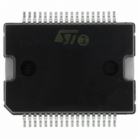
L6228PD STMicroelectronics, L6228PD Datasheet - Page 20

L6228PD
Manufacturer Part Number
L6228PD
Description
IC DRIVER STEP MOTOR 36-PWRSOIC
Manufacturer
STMicroelectronics
Type
Driverr
Datasheet
1.L6228DTR.pdf
(26 pages)
Specifications of L6228PD
Applications
Stepper Motor Driver
Number Of Outputs
1
Current - Output
1.4A
Voltage - Supply
8 V ~ 52 V
Operating Temperature
-25°C ~ 125°C
Mounting Type
Surface Mount
Package / Case
36-PowerSOIC
Operating Current
10mA
Operating Temperature Classification
Automotive
Package Type
PowerSO
Operating Supply Voltage (min)
8V
Operating Supply Voltage (typ)
48V
Operating Supply Voltage (max)
52V
Product
Stepper Motor Controllers / Drivers
Operating Supply Voltage
8 V to 52 V
Supply Current
1.4 A
Mounting Style
SMD/SMT
For Use With
497-6818 - EVAL BOARD FOR L6228Q
Lead Free Status / RoHS Status
Lead free / RoHS Compliant
Voltage - Load
-
Lead Free Status / Rohs Status
Compliant
Other names
497-5351-5
L6228PD
L6228PD
Available stocks
Company
Part Number
Manufacturer
Quantity
Price
Part Number:
L6228PD
Manufacturer:
ST
Quantity:
20 000
Part Number:
L6228PD013TR
Manufacturer:
ST
Quantity:
20 000
Part Number:
L6228PDTR
Manufacturer:
ST
Quantity:
20 000
L6228
Output Current Capability and IC Power Dissipation
In Fig. 24, 25, 26 and 27 are shown the approximate relation between the output current and the IC power dis-
sipation using PWM current control driving a two-phase stepper motor, for different driving sequences:
– HALF STEP mode (Fig. 24) in which alternately one phase / two phases are energized.
– NORMAL DRIVE (FULL-STEP TWO PHASE ON) mode (Fig. 25) in which two phases are energized
– WAVE DRIVE (FULL-STEP ONE PHASE ON) mode (Fig. 26) in which only one phase is energized at
– MICROSTEPPING mode (Fig. 27), in which the current follows a sine-wave profile, provided through
For a given output current and driving sequence the power dissipated by the IC can be easily evaluated, in order
to establish which package should be used and how large must be the on-board copper dissipating area to guar-
antee a safe operating junction temperature (125°C maximum).
Figure 24. IC Power Dissipation versus Output Current in HALF STEP Mode.
Figure 25. IC Power Dissipation versus Output Current in NORMAL Mode (full step two phase on).
20/26
during each step.
each step.
the V
ref
pins.
P
P
D
D
[W ]
[W]
10
10
8
6
4
2
0
8
6
4
2
0
0
0 0.25 0.5 0.75 1 1.25 1.5
0.25 0.5 0.75 1
NORM AL DRIVE
HALF STEP
I
I
OUT
OUT
[A ]
[A]
1.25 1.5
I
I
A
B
I
I
A
B
Test Conditions:
Supply Voltage = 24V
Test Conditions:
Supply Volt age = 24 V
I
OUT
I
No PWM
f
OUT
SW
I
No PWM
f
= 30 kHz (slow decay)
OUT
SW
= 30 kHz (slow decay)
I
OUT


