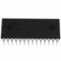
MC3PHACVPE Freescale Semiconductor, MC3PHACVPE Datasheet - Page 10

MC3PHACVPE
Manufacturer Part Number
MC3PHACVPE
Description
IC MOTOR CONTROLLER 28-DIP
Manufacturer
Freescale Semiconductor
Datasheet
1.MC3PHACVFAE.pdf
(36 pages)
Specifications of MC3PHACVPE
Applications
AC Motor Controller, 3 Phase
Number Of Outputs
1
Voltage - Supply
4.5 V ~ 5.5 V
Operating Temperature
-40°C ~ 105°C
Mounting Type
Through Hole
Package / Case
28-DIP (0.600", 15.24mm)
Processor Series
MC3PHAC
Core
HC08
Data Bus Width
8 bit
Program Memory Type
Flash
Program Memory Size
8 KB
Data Ram Size
256 KB
Interface Type
RS-232
Maximum Clock Frequency
21.16 KHz
Number Of Programmable I/os
14
Number Of Timers
1
Operating Supply Voltage
5 V
Maximum Operating Temperature
+ 105 C
Mounting Style
Through Hole
Minimum Operating Temperature
- 40 C
On-chip Adc
10 bit, 4 Channel
Controller Family/series
HC08
Core Size
8 Bit
Ram Memory Size
256Byte
Embedded Interface Type
SCI
Digital Ic Case Style
DIP
No. Of Pins
28
A/d Converter
10 Bits
No. Of Timers 8/12/16/32 Bits
0/0/2/0
Rohs Compliant
Yes
Lead Free Status / RoHS Status
Lead free / RoHS Compliant
Current - Output
-
Voltage - Load
-
Lead Free Status / Rohs Status
Lead free / RoHS Compliant
Available stocks
Company
Part Number
Manufacturer
Quantity
Price
Company:
Part Number:
MC3PHACVPE
Manufacturer:
TE
Quantity:
1 001
Features
In standalone mode, the base frequency and PWM polarity are specified at the same time during
initialization by connecting either pin 25, 26, 27, or 28 exclusively to the PWMPOL_BASEFREQ input.
During initialization, pins 25, 26, 27, and 28 are cycled one at a time to determine which one has been
connected to the PWMPOL_BASEFREQ input.
Table 3
made. Refer to the standalone mode schematic,
connected at any one time.
10
shows the selected PWM polarity and base frequency as a function of which pin connection is
Table 3. PWM Polarity and Base Frequency Specification in Standalone Mode
PWMPOL_BASEFREQ Pin
It is not necessary to break this connection once the initialization phase has
been completed. The MC3PHAC will function properly while this
connection is in place.
MOTOR PHASE CURRENT WAVEFORMS
Pin Connected to
DC_BUS (JP4)
MUX_IN (JP1)
UNCOMPENSATED
SPEED (JP2)
ACCEL (JP3)
COMPENSATED
MC3PHAC Monolithic Intelligent Motor Controller, Rev. 2
Figure 4. Dynamic Bus Ripple Cancellation
NOTE
Figure
REMOVES 60 Hz HUM
AND DECREASES I
MC3PHAC
Logic high = on
Logic high = on
PWM Polarity
Logic low = on
Logic low = on
8. Only one of these jumpers (JP1–JP4) can be
PWM1
PWM2
CORRECTED PWMs
2
R LOSSES
PWM3
PWM4
Base Frequency
PWM5
PWM6
Freescale Semiconductor
50 Hz
50 Hz
60 Hz
60 Hz


