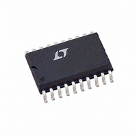
LT1509ISW#TR Linear Technology, LT1509ISW#TR Datasheet - Page 8

LT1509ISW#TR
Manufacturer Part Number
LT1509ISW#TR
Description
IC PFC CTRLR AVERAGE CURR 20SOIC
Manufacturer
Linear Technology
Datasheet
1.LT1509CN.pdf
(16 pages)
Specifications of LT1509ISW#TR
Mode
Average Current
Frequency - Switching
100kHz
Voltage - Supply
27V
Operating Temperature
-40°C ~ 125°C
Mounting Type
Surface Mount
Package / Case
20-SOIC (7.5mm Width)
Lead Free Status / RoHS Status
Contains lead / RoHS non-compliant
Current - Startup
-
Lead Free Status / Rohs Status
Not Compliant
Available stocks
Company
Part Number
Manufacturer
Quantity
Price
APPLICATIONS
8
LT1509
Current Amplifier (PFC Section)
The current amplifier has a 110dB DC gain, 3MHz unity-
gain frequency and a 2V/ s slew rate. It is internally
clamped at 8.5V. Note that in the current averaging opera-
tion, high gain at twice the line frequency is necessary to
minimize line current distortion. Because CA
to swing 5V over one line cycle at high line condition,
20mV AC will be needed at the inputs of the current
amplifier for a gain of 260 at 120Hz. Especially at light load
when the current loop reference signal is small, lower gain
will distort the reference signal and line current. But, if
signal gain at switching frequency is too high, the system
behaves more like a current mode system and can cause
subharmonic oscillation.
V
IN
V
IN
R
1M
IAC
–20
–40
80
60
40
20
0
0.1
–
+
I
AC
V
I
I
IN
M
IN
U
1
FREQUENCY (Hz)
M
R
4k
0.15
REF
OUT
INFORMATION
Figure 2
Figure 3
R
L
U
S
10
I
R5
4k
SENSE
20k
R6
100
W
–
+
300pF
LT1509 • F03
C4
CA
D1
1k
0.001 F
OUT
60
45
30
15
0
–15
–30
C3
V
U
may need
OUT
LT1509
CA
C
470 F
OUT
1509 • F02
OUT
To avoid subharmonic oscillations, the amplified downslope
of the inductor current must be less than the slope of the
oscillator ramp.
If the current amplifier gain at 100kHz is less than 4.4,
there will be no subharmonic oscillation. The open-loop
gain of the current loop is given by:
The current error amp, with R5 = 4k, R6 = 20k, C3 =
0.001 F and C4 = 300pF, provides zero pole compensa-
tion resulting in 16kHz loop crossover frequency. The
current amp gain at 100kHz is 1.7. The resulting current
loop gain and phase margin is shown in Figure 4.
Multiplier
The multiplier has high noise immunity and superior
linearity over its full operating range. The current gain is
I
error amplifier output voltage required at the input to the
multiplier is:
M
=
= (I
V
=
V
CA(OUT)
(5V)(500 H)(100k)
CA(OUT)
(j)(2 f)(500 H)(5V)
V
V
AC
(382V)(0.15 )
RS
RS
(382V)(0.15 )
I
EA
–20
–40
80
60
40
20
2
0
)/(200 A
100
=
(V
(j)(2 f)(L)(V
(V
OSC
(V
OUT
1k
2
OUT
)(L)(f
) with I
FREQUENCY (Hz)
)(R
Figure 4
)(R
= 4.4
=
S
10k
SW
3648
(j)(f)
)
S
OSC
EA
)
)
= (VA
)
100k
OUT
LT1509 • F04
– 2V)/ 25k. The
1M
60
45
30
15
0
–15
–30


