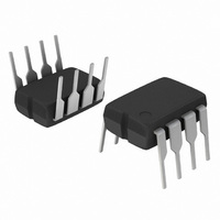
MC33262PG ON Semiconductor, MC33262PG Datasheet - Page 10

MC33262PG
Manufacturer Part Number
MC33262PG
Description
IC PFC CONTROLLER CRM 8DIP
Manufacturer
ON Semiconductor
Datasheet
1.MC34262DG.pdf
(19 pages)
Specifications of MC33262PG
Mode
Critical Conduction (CRM)
Current - Startup
250µA
Voltage - Supply
12 V ~ 28 V
Operating Temperature
-40°C ~ 105°C
Mounting Type
Through Hole
Package / Case
8-DIP (0.300", 7.62mm)
Maximum Operating Temperature
+ 105 C
Mounting Style
Through Hole
Minimum Operating Temperature
- 40 C
Lead Free Status / RoHS Status
Lead free / RoHS Compliant
Frequency - Switching
-
Lead Free Status / Rohs Status
Lead free / RoHS Compliant
Other names
MC33262PGOS
Available stocks
Company
Part Number
Manufacturer
Quantity
Price
Company:
Part Number:
MC33262PG
Manufacturer:
ON
Quantity:
5 510
Company:
Part Number:
MC33262PG
Manufacturer:
ON Semiconductor
Quantity:
8 150
Part Number:
MC33262PG
Manufacturer:
ON/安森美
Quantity:
20 000
The following converter characteristics must be chosen:
Table 1. Design Equations
Calculate the maximum required output power.
Calculated at the minimum required ac line voltage
for output regulation. Let the efficiency η = 0.92 for
low line operation.
Let the switching cycle t = 40 ms for universal input
(85 to 265 Vac) operation and 20 ms for fixed input
(92 to 138 Vac, or 184 to 276 Vac) operation.
In theory the on- -time t
tends to increase at the ac line zero crossings due
to the charge on capacitor C
t
The off- -time t
voltage and approaches zero at the ac line zero
crossings. Theta (θ) represents the angle of the ac
line voltage.
The minimum switching frequency occurs at the peak
of the ac line voltage. As the ac line voltage traverses
from peak to zero, t
increase in switching frequency.
Set the current sense threshold V
universal input (85 Vac to 265 Vac) operation and
to 0.5 V for fixed input (92 Vac to 138 Vac, or
184 Vac to 276 Vac) operation. Note that V
be <1.4 V.
Set the multiplier input voltage V
line. Empirically adjust V
over the ac line voltage range while guaranteeing
startup at minimum line.
The I
current in excess of 50 mA.
The calculated peak- -to- -peak ripple must be less than
16% of the average dc output voltage to prevent false
tripping of the Overvoltage Comparator. Refer to the
Overvoltage Comparator text. ESR is the equivalent
series resistance of C
The bandwidth is typically set to 20 Hz. When operating
at high ac line, the value of C
increased. (See Figure 25)
on
ΔV
and t
V
I
IB
O
O
O
- - Desired output voltage
- - Desired output current
R
- - Converter output peak- -to- -peak ripple voltage
off
1
error term can be minimized with a divider
calculations.
off
is greatest at the peak of the ac line
off
3
approaches zero producing an
on
.
Notes
is constant. In practice t
M
for the lowest distortion
5
1
. Let Vac = Vac
may need to be
M
CS
to 3.0 V at high
to 1.0 V for
Vac
(LL)
CS
Vac - - AC RMS line voltage
(LL)
for initial
on
must
- - AC RMS low line voltage
http://onsemi.com
Required Converter Output Power
Peak Inductor Current
Inductance
Switch On- -Time
Switch Off- -Time
Switching Frequency
Peak Switch Current
Multiplier Input Voltage
Converter Output Voltage
Error Amplifier Bandwidth
Converter Output
Peak to Peak
Ripple Voltage
10
Calculation
ΔV
L
P
V
O(pp)
t
=
off
O
t
= V
=
V
I
= I
L(pk)
V
ref
M
O
BW =
2
O
t
R
=
f =
on
P
7
Formula
2 Vac Sin θ
O
=
- - Vac
=
=
R
R
= V
t
2 V
on
Vac
2
1
R
R
ηVac
V
2 P
2 2 P
2 π C
I
η Vac
V
5
3
L(pk)
O
+ t
+ 1
2πf
O
(LL)
1
O
t
gm
CS
on
O
+ 1
I
P
off
O
ac
(LL)
1
O
L
2
1
2
P
O
C
- - I
η Vac
3
IB
- - 1
2
+ ESR
R
(LL)
2
2
2


