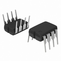
MC33262PG ON Semiconductor, MC33262PG Datasheet - Page 15

MC33262PG
Manufacturer Part Number
MC33262PG
Description
IC PFC CONTROLLER CRM 8DIP
Manufacturer
ON Semiconductor
Datasheet
1.MC34262DG.pdf
(19 pages)
Specifications of MC33262PG
Mode
Critical Conduction (CRM)
Current - Startup
250µA
Voltage - Supply
12 V ~ 28 V
Operating Temperature
-40°C ~ 105°C
Mounting Type
Through Hole
Package / Case
8-DIP (0.300", 7.62mm)
Maximum Operating Temperature
+ 105 C
Mounting Style
Through Hole
Minimum Operating Temperature
- 40 C
Lead Free Status / RoHS Status
Lead free / RoHS Compliant
Frequency - Switching
-
Lead Free Status / Rohs Status
Lead free / RoHS Compliant
Other names
MC33262PGOS
Available stocks
Company
Part Number
Manufacturer
Quantity
Price
Company:
Part Number:
MC33262PG
Manufacturer:
ON
Quantity:
5 510
Company:
Part Number:
MC33262PG
Manufacturer:
ON Semiconductor
Quantity:
8 150
Part Number:
MC33262PG
Manufacturer:
ON/安森美
Quantity:
20 000
Comparator
A narrow turn- -on spike is usually present on the leading edge of
the current waveform and can cause circuit instability. The
MC34262 provides an internal RC filter with a time constant of
220 ns. An additional external RC filter may be required in
universal input applications that are above 200 W. It is
suggested that the external filter be placed directly at the Current
Sense Input and have a time constant that approximates the
spike duration.
Current
Sense
Figure 27. Current Waveform Spike Suppression
The Error Amp output is a high impedance node and is susceptible to noise pickup. To minimize pickup, compensation
capacitor C
operating at high ac line, the voltage at Pin 2 may approach the lower threshold of the Multiplier, 2.0 V. If there is
excessive ripple on Pin 2, the Multiplier will be driven into cut- -off causing circuit instability, high distortion and poor power
factor. This problem can be eliminated by increasing the value of C
1
must be connected as close to Pin 2 as possible with a short, heavy ground returning directly to Pin 6. When
10pF
22k
7
4
Figure 26. Error Amp Compensation
6
C
R
C
1
http://onsemi.com
R
2
10mA
7
Error Amp
15
Comparator
+
A negative turn- -off spike can be observed on the trailing edge of
the current waveform. This spike is due to the parasitic
inductance of resistor R
circuit instability. The addition of Schottky diode D
effectively clamp the negative spike. The addition of the external
RC filter shown in Figure 26 may provide sufficient spike
attenuation.
Current
Sense
1
.
1
Figure 28. Negative Current Waveform
R
R
2
1
Spike Suppression
7
10pF
, and if it is excessive, it can cause
22k
7
4
D
1
1
can
R
7


