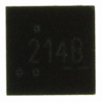
FPF2214 Fairchild Semiconductor, FPF2214 Datasheet

FPF2214
Specifications of FPF2214
Available stocks
Related parts for FPF2214
FPF2214 Summary of contents
Page 1
... The FPF2213 has an auto-restart feature, which will turn the switch on again after 450mS if the ON pin is still active. The FPF2214 do not have this auto-restart feature so the switch will remain off until the ON pin is cycled. For the FPF2215, a current limit condition will immediately pull ...
Page 2
Typical Application Circuit OFF ON Functional Block Diagram V IN UVLO THERMAL SHUTDOWN ON FPF2213-FPF2215 Rev. C FPF2213/4 OUT IN FLAGB ON I SET GND CONTROL LOGIC CURRENT LIMIT Output Discharge GND 2 TO LOAD V OUT I ...
Page 3
Pin Configuration Pin Description Pin Name 1 I SET OUT 4 FLAGB 5 GND 6 ON Absolute Maximum Ratings Parameter ON, FLAGB TO GND IN OUT I TO GND SET Power ...
Page 4
... Hysteresis UVLO V increasing =500 , C =0.001uF =500 , C =0.001uF OFF =500 , C =0.001uF RISE =500 , C =0.001uF FALL FPF2213, FPF2214 BLANK t FPF2213 RSTRT 3.3V. Over-Current IN ON Condition /(I x4) LOAD IN LIM 4 Min. Typ. Max. Units 1 250 325 275 360 350 455 135 450 72 105 0.8 1.4 ...
Page 5
Typical Characteristics - SUPPLY VOLTAGE (V) Figure 1. Quiescent Current vs. Input Voltage 1.6 1.4 1.2 V ...
Page 6
Typical Characteristics 300 250 200 150 100 (V) IN OUT Figure 7. Current Limit vs. Output Voltage 470 430 390 350 310 270 230 o -40 ...
Page 7
Typical Characteristics V IN 2V/DIV I OUT 10mA/DIV V ON 2V/DIV V OUT 2V/DIV 100 s/DIV Figure 13. Turn On Reponse V =3.3V =10uF =1uF, OUT V R =26.8K ON SET 2V/DIV ...
Page 8
Typical Characteristics V ON 2V/DIV I I OUT OUT 200mA/DIV 200mA/DIV V V FLAG FLAG 2V/DIV 2V/DIV V OUT 2V/DIV 500 s/DIV Figure 19. Current Limit Response (Output is loaded with large capacitor) FPF2213-FPF2215 Rev =3.3V ...
Page 9
... FLAGB signals the fault mode by activating LO. In the event of an over-current condition for the FPF2213 and FPF2214, the FLAGB goes LO at the end of the blanking time while FLAGB goes LO immediately for the FPF2215. If the over-current condition lasts longer than ...
Page 10
... I LIM (Min) GND. This capacitor will prevent parasitic board inductances from forcing V FPF2213 and FPF2214, the total output capacitance needs to be kept below a maximum value, C part from registering an over-current condition and turning-off the switch. The maximum output capacitance can be determined from the following formula: ...
Page 11
Take note that this is below the maximum package power dissipation, and the thermal shutdown feature will act as additional safety to protect the part from damage due to excessive heating. The junction temperature is only able to increase to ...
Page 12
Figure 25: Proper layout of output and ground copper area FPF22XX Demo Board FPF22XX Demo board has components and circuitry to demonstrate FPF2213/4/5 load switches functions and features. R4 resistor with 0 value is used for measuring the output current. ...
Page 13
Dimensional Outline and Pad Layout FPF2213-FPF2215 Rev www.fairchildsemi.com ...
Page 14
... TRADEMARKS The following are registered and unregistered trademarks and service marks Fairchild Semiconductor owns or is authorized to use and is not intended exhaustive list of all such trademarks. ® ACEx Build it Now™ CorePLUS™ CROSSVOLT™ CTL™ Current Transfer Logic™ ® ...


