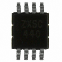
ZXSC440X8TA Diodes Zetex, ZXSC440X8TA Datasheet

ZXSC440X8TA
Specifications of ZXSC440X8TA
Related parts for ZXSC440X8TA
ZXSC440X8TA Summary of contents
Page 1
... Consumes only 4.5 A when not charging • Small MSOP8 low profile package PINOUT MSOP8 pin TOP VIEW ORDERING INFORMATION DEVICE DEVICE DESCRIPTION ZXSC440X8TA Camera flash charger ZXSC440X8TC • TA reels hold 1000 devices • TC reels hold 4000 devices ISSUE 1 - JANUARY 2005 The Ready pin signals the microprocessor when the flash is charged and ready to be fired ...
Page 2
ZXSC440 ABSOLUTE MAXIMUM RATINGS PARAMETER V CC DRIVE READY CHARGE V , SENSE FB Operating temperature Storage temperature Power dissipation at 25°C ELECTRICAL CHARACTERISTICS SYMBOL PARAMETER V V range CC CC (1) Iq Quiescent current I Shutdown current STDN (2) ...
Page 3
ABSOLUTE MAXIMUM RATINGS PIN # NAME DESCRIPTION 1 DRIVE Drive output for external switching transistor. Connect to base or gate of external switching transistor 2 V Reference voltage. Internal threshold set to 300mV. Connect external resistor FB network to set ...
Page 4
ZXSC440 DEVICE DESCRIPTION Bandgap reference All threshold voltages and internal currents are derived from a temperature compensated bandgap reference circuit with a reference voltage of 1.22V nominal. If the REF terminal is used as a reference for external devices, the ...
Page 5
TYPICAL OPERATING CHARACTERISTICS (For typical application circuit at V ISSUE 1 - JANUARY 2005 =3V and T =25 °C unless otherwise stated ZXSC440 ...
Page 6
ZXSC440 APPLICATIONS Switching transistor selection The choice of switching transistor has a major impact on the converter efficiency. For optimum performance, a bipolar transistor with low V CE(SAT) required. The V of the switching transistor is also an CEO important ...
Page 7
Transformer parameters Proprietary transformers are available, for example the Pulse PAO367, Primary inductance: 24uH, Core: Pulse PAO367, Turns ratio: 1:12, see Bill of Materials below. If designing a transformer, bear in mind that the primary current may be over an ...
Page 8
ZXSC440 Output power calculation This is approximately the power stored in the coil times the frequency of operation times the efficiency. Assuming a current of 1.2 amps in a 30µH primary, the stored energy will be 21.6µJ. The frequency is ...
Page 9
Layout issues Layout is critical for the circuit to function in the most efficient manner in terms of electrical efficiency, thermal considerations and noise. For 'step-up converters' there are four main current loops, the input loop, power-switch loop, rectifier loop ...
Page 10
ZXSC440 REFERENCE DESIGNS General camera photoflash charger Specification 275V OUT Efficiency = 71% Charging time = 4 seconds Bill of materials Ref Value Package U1 MSOP8 Q1 SOT23 (2) D1 200V SOT23 Tx1 R1 ...
Page 11
High power digital camera photoflash charger Specification 275V OUT Efficiency = 69% Charging time = 5 seconds Bill of materials Ref Value Package U1 MSOP8 U2 SOT23-6 Q1 SOT23 D1 200V SOT23 D2 200V ...
Page 12
ZXSC440 Low power digital camera photoflash charger Specification 275V OUT Efficiency = 58% Charging time = 6.8 seconds Bill of materials Ref Value Package U1 MSOP8 U2 SOT23-6 Q1 SOT23 D1 200V SOT23 D2 ...
Page 13
NOTES: ISSUE 1 - JANUARY 2005 13 ZXSC440 ...
Page 14
ZXSC440 NOTES ISSUE 1 - JANUARY 2005 14 ...
Page 15
NOTES: ISSUE 1 - JANUARY 2005 15 ZXSC440 ...
Page 16
ZXSC440 PACKAGE OUTLINE 8 1 INDENT AREA (D/2 X E1/2) Controlling dimensions are in millimeters. Approximate conversions are given in inches PACKAGE DIMENSIONS Millimeters Inches DIM Min Max Min Max A - 1.10 - 0.0433 A1 0.05 0.15 0.002 0.006 ...


