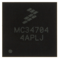
MC34704AEP Freescale Semiconductor, MC34704AEP Datasheet - Page 23

MC34704AEP
Manufacturer Part Number
MC34704AEP
Description
IC POWER MANAGEMENT 56-QFN
Manufacturer
Freescale Semiconductor
Datasheet
1.MC34704BEPR2.pdf
(54 pages)
Specifications of MC34704AEP
Applications
Processor
Current - Supply
86mA
Voltage - Supply
2.7 V ~ 5.5 V
Operating Temperature
-20°C ~ 85°C
Mounting Type
Surface Mount
Package / Case
56-QFN
Output Voltage
5 V
Input Voltage
2.7 V to 5.5 V
Switching Frequency
750 KHz to 2 MHz
Mounting Style
SMD/SMT
Number Of Outputs
8
Lead Free Status / RoHS Status
Lead free / RoHS Compliant
when REG3 is powered up in the sequence.
allow pulse skipping.
shutting down and it will be held low by the discharge FET as
long as possible.
Characteristics
• It powers up directly from the battery
• Operates at a switching frequency equals to F
• Drives integrated low R
• The output is ±4% accuracy
• Output voltage is adjustable by means of an external
• The output can be adjusted up or down at 2.5% steps to
• An extra fine voltage scaling in 0.5% steps helps to adjust
• Uses a bootstrap network with an internal diode to power
• All gate drive circuits are supplied from VG.
• Uses integrated compensation.
• The output is monitored for under-voltage and over-
• The output is monitored for over-current and short-circuit
• The regulator is monitored for over-temperature conditions
Operation Modes
• VG is in regulation AND
• There is no GrpB shutdown command through the I
• No faults exist that would cause GrpB to shut down
REG4
mode control DC/DC regulator.
when REG4 is powered up in the sequence.
allow pulse skipping.
shutting down and it will be held low by the discharge FET as
long as possible.
Characteristics
• It powers up directly from the battery
• Operates at a switching frequency equals to F
Analog Integrated Circuit Device Data
Freescale Semiconductor
See Power-Up Sequence on page 28
The switcher will operate in DCM at very light loads to
VOUT3 will be discharged every time the regulator is
MOSFETs (NHV_HC) as its output stage
resistor divider
achieve from +17.5% to -20.0% on each direction allowing
Dynamic Voltage Scaling using the I
down the output voltage as low as 40%.
its switch MOSFET
voltage conditions
conditions
The switcher will be active when:
interface AND
This is a 4-switch synchronous buck-boost PWM voltage-
See Power-Up Sequence on page 28
The switcher will operate in DCM at very light loads to
VOUT4 will be discharged every time the regulator is
DS(ON)
N-channel power
2
C DVS register.
for more details on
for more details on
SW1
SW1
2
C
• Drives integrated low R
• The output is ±2% accuracy
• Output voltage is adjustable by means of an external
• The output can be adjusted up or down at 2.5% steps for
• Uses bootstrap networks with an internal diode to power
• All gate drive circuits are supplied from VG.
• Uses external compensation
• The output is monitored for under-voltage and over-
• The output is monitored for over-current and short-circuit
• The regulator is monitored for over-temperature conditions
Operation Modes
• VG is in regulation AND
• There is no GrpB shutdown command through the I
• No faults exist that would cause GrpB to shut down
REG5
mode control DC/DC regulator.
on when REG5 is powered up in the sequence.
allow pulse skipping.
shutting down and it will be held low by the discharge FET as
long as possible.
Characteristics
• It powers up directly from the battery
• Operates at a switching frequency equals to F
• Drives integrated low R
• The output is ±2% accuracy
• Output voltage is adjustable by means of an external
• The output can be adjusted up or down at 2.5% steps for
• Uses bootstrap networks with an internal diodes to power
• All gate drive circuits are supplied from VG.
• Uses external compensation
• The output is monitored for under-voltage and over-
MOSFETs (NHV_HC) as its output stage
resistor divider
a total of +17.5% to -20.0% on each direction allowing
Dynamic Voltage Scaling.
its high side MOSFETs
voltage conditions
conditions
The switcher will be active when:
interface AND
This is a 4-switch synchronous buck-boost PWM voltage-
See Power-Up Sequence on page 28
The switcher will operate in DCM at very light loads to
VOUT5 will be discharged every time the regulator is
MOSFETs (NHV_HC) as its output stage
resistor divider
a total of +17.5% to -20.0% on each direction allowing
Dynamic Voltage Scaling.
its high side MOSFETs
voltage conditions
FUNCTIONAL INTERNAL BLOCK DESCRIPTION
DS(ON)
DS(ON)
FUNCTIONAL DESCRIPTION
N-channel power
N-channel power
on for more details
SW1
2
C
34704
23


