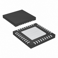
MAX1702BETX+ Maxim Integrated Products, MAX1702BETX+ Datasheet - Page 15

MAX1702BETX+
Manufacturer Part Number
MAX1702BETX+
Description
IC PWR MNG TRPL OUT 36-TQFN
Manufacturer
Maxim Integrated Products
Datasheet
1.MAX1702BETX.pdf
(19 pages)
Specifications of MAX1702BETX+
Applications
Processor
Voltage - Supply
2.6 V ~ 5.5 V
Operating Temperature
-40°C ~ 85°C
Mounting Type
Surface Mount
Package / Case
36-TQFN Exposed Pad
Lead Free Status / RoHS Status
Lead free / RoHS Compliant
Current - Supply
-
Lead Free Status / Rohs Status
Lead free / RoHS Compliant
Compensate each regulator by placing a resistor and a
capacitor in series, from COMP_ to GND and connect a
33pF capacitor from COMP_ to GND for improved
noise immunity (Figure 1). The capacitor integrates the
current from the transconductance amplifier, averaging
output-voltage ripple. This sets the device speed for
transient responses and allows the use of small ceram-
ic output capacitors. The resistor sets the proportional
gain of the output error voltage by a factor g
Increasing this resistor also increases the sensitivity of
the control loop to the output-voltage ripple.
This resistor and capacitor set a compensation zero
that defines the system’s transient response. The load
pole is a dynamic pole, shifting frequency with changes
in load. As the load decreases, the pole frequency
shifts lower. System stability requires that the compen-
sation zero must be placed properly to ensure ade-
quate phase margin (at least 30°). The following is a
design procedure for the compensation network:
1) Select an appropriate converter bandwidth (f
2) Calculate the compensation capacitor, COMP_,
Calculate the equivalent load impedance, R
where V
I
OUT(MAX)
C
COMP
stabilize the system while maximizing transient
response. This bandwidth should not exceed 1/5 of
the switching frequency. Use 100kHz as a reason-
able starting point.
based on this bandwidth. Calculate COMP1 and
COMP3 with the following equation:
where RCS is the regulator’s current-sense transre-
sistance and gm is the regulators error amplifier
transconductance. Calculate COMP2 with the fol-
lowing equation:
where R
and g
C
COMP
OUT(MIN)
2
m
=
equals the maximum load current. Choose
1 3
is REG2’s error-amplifier transconductance.
CS
/
V
I
OUT MAX
OUT MAX
=
is REG2’s current-sense transresistance
(
V
I
(
R
equals the minimum output voltage.
______________________________________________________________________________________
OUT MAX
OUT MAX
Compensation and Stability
L
Triple-Output Power-Management IC for
=
)
(
)
(
I
V
OUT MAX
OUT MIN
R
)
CS
1
)
(
(
R
2
CS
)
1
)
× ×
1
π
2
f
× ×
Microprocessor-Based Systems
1
π
g
m
L
f
, by:
×
R
g
m
m
4
R
+
✕
5
C
R
) to
R
5
C
.
the output capacitor, C
Selection section). Calculate the compensation resis-
tance (R
ed by the output load and the output capacitance:
Solving for R
To find C
pensation pole to cancel the zero created by the output
capacitor’s equivalent series resistance (ESR):
Solving for C
If low-ESR ceramic capacitors are used, the C
equation can yield a very small capacitance value. In
such cases, do not use less than 33pF to maintain
noise immunity.
A 4.7µH inductor with a saturation current of at least
1.5A is recommended for most applications. For best
efficiency, use an inductor with low ESR. See Table 1
for recommended inductors and manufacturers. For
most designs, a reasonable inductor value (L
be derived from the following equation:
where LIR is the inductor current ripple as a percent-
age of the load current.
LIR should be kept between 20% and 40% of the maxi-
mum load current for best performance and stability.
The maximum inductor current is:
C
COMPHF
2
× ×
π
C
2
COMPHF_
) value to cancel out the dominant pole creat-
L
× ×
R
IDEAL
_
ESR
π
C
I
COMPHF_
LMAX
=
1
gives:
R
R
×
ESR
1
L
=
C
, calculate the high-frequency com-
×
=
V
R
OUT
R
IN
C
C
×
C
1
OUT
C
gives:
×
=
+
OUT
V
OUT
LIR I
R
=
LIR
OUT IN
C
2
L
2
=
COMP
×
×
× ×
,
(see the Output Capacitor
2
(
but not less than
OUT MAX
C
V
π
× ×
I
OUT MAX
OUT
Inductor Selection
π
_
R
−
(
C
V
(
RC C
OUT
×
1
)
C
1
×
×
)
COMPHF_
)
f
OSC
COMP_
IDEAL
COMPHF_
33
) can
pF
15


