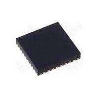
MAX15048ETJ+ Maxim Integrated Products, MAX15048ETJ+ Datasheet - Page 22

MAX15048ETJ+
Manufacturer Part Number
MAX15048ETJ+
Description
IC CTRLR PWM STP-DN TRIPL 32WQFN
Manufacturer
Maxim Integrated Products
Datasheet
1.MAX15048ETJ.pdf
(31 pages)
Specifications of MAX15048ETJ+
Applications
Power Supply Controller, Sequencer
Voltage - Supply
4.7 V ~ 23 V
Current - Supply
6mA
Operating Temperature
-40°C ~ 85°C
Mounting Type
Surface Mount
Package / Case
32-WQFN Exposed Pad
Number Of Outputs
3
Output Voltage
5 V
Input Voltage
4.7 V to 23 V
Supply Current
6 mA
Switching Frequency
200 KHz
Mounting Style
SMD/SMT
Maximum Operating Temperature
+ 85 C
Minimum Operating Temperature
- 40 C
Lead Free Status / RoHS Status
Lead free / RoHS Compliant
Voltage - Input
-
Lead Free Status / Rohs Status
Lead free / RoHS Compliant
Triple-Output Buck Controllers
with Tracking/Sequencing
Below are equations that define the power modulator:
The switching frequency is programmable between
200kHz and 1.2MHz using an external resistor at RT.
Typically, the crossover frequency (f
frequency when the system’s closed-loop gain is equal
to unity, crosses the 0dB axis, and should be set at or
below 1/10 the switching frequency (f
closed-loop response.
The MAX15048/MAX15049 provide an internal transcon-
ductance amplifier with its inverting input and its output
available to the user for external frequency compensation.
The flexibility of external compensation for each con-
verter offers wide selection of output-filtering components,
Figure 4a. Power Modulator Gain and Phase Response (Large, Bulk C
22
_____________________________________________________________________________________
f
ZERO, ESR
f
f
LC
ZERO, ESL
G
MOD(DC)
=
-20
-40
-60
-80
2
=
40
20
π ×
0
2
=
π ×
=
L C
V
1
2
×
ESR C
RAMP
π ×
V
ESR
IN
OUT
1
ESL
×
|G
CO
SW
MOD
OUT
), which is the
/10) for stable,
| ASYMPTOTE
< G
MOD
f
LC
FREQUENCY (Hz)
f
ZERO, ESR
especially the output capacitor. For cost-sensitive appli-
cations, use aluminum electrolytic capacitors; for space-
sensitive applications, use low ESR tantalum or multilayer
ceramic chip (MLCC) capacitors at the output. The higher
switching frequencies of the MAX15048/MAX15049 allow
the use of MLCC as the primary filter capacitor(s).
First, select the passive and active power compo-
nents that meet the application’s output ripple, compo-
nent size, and component cost requirements. Second,
choose the small-signal compensation components to
achieve the desired closed-loop frequency response
and phase margin as outlined below.
The power modulator’s LC lowpass filter exhibits a vari-
ety of responses, depending on the value of L and C
(and their parasitics).
One such response is shown in Figure 4a. In this exam-
ple, the power modulator’s uncompensated crossover
is approximately 1/6 the desired crossover frequency,
f
plane follows the double-pole, -40dB/decade slope and
approaches 180° of phase shift, indicative of a poten-
tially unstable system. Together with the inherent 180° of
phase delay in the negative feedback system, this can
lead to near 360°, or “positive” feedback—an unstable
system.
CO
|G
OUT
MOD
. Note also, the uncompensated rolloff through 0dB
)
|
f
ZERO, ESL
Closed-Loop Response and Compensation
of Voltage-Mode Regulators
90
45
0
-45
-90
-135
-180


