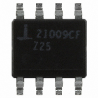
ISL21009CFB825Z-TK Intersil, ISL21009CFB825Z-TK Datasheet - Page 4

ISL21009CFB825Z-TK
Manufacturer Part Number
ISL21009CFB825Z-TK
Description
IC VOLT REF FGA LV 2.5V 8-SOIC
Manufacturer
Intersil
Series
FGA™r
Datasheet
1.ISL21009DFB850Z-TK.pdf
(19 pages)
Specifications of ISL21009CFB825Z-TK
Reference Type
Series
Voltage - Output
2.5V
Tolerance
±1mV
Temperature Coefficient
5ppm/°C
Voltage - Input
3.5 ~ 16.5 V
Number Of Channels
1
Current - Quiescent
180µA
Current - Output
7mA
Operating Temperature
-40°C ~ 125°C
Mounting Type
Surface Mount
Package / Case
8-SOIC (3.9mm Width)
Rohs Compliant
Yes
Lead Free Status / RoHS Status
Lead free / RoHS Compliant
Current - Cathode
-
Other names
ISL21009CFB825Z-TKTR
Available stocks
Company
Part Number
Manufacturer
Quantity
Price
Company:
Part Number:
ISL21009CFB825Z-TK
Manufacturer:
Intersil
Quantity:
1 792
Part Number:
ISL21009CFB825Z-TK
Manufacturer:
INTERSIL
Quantity:
20 000
Common Electrical Specifications (ISL21009-12, -25, -41, -50)
Absolute Voltage Ratings
Max Voltage V
Max Voltage V
Voltage on “DNC” pins . . . . No connections permitted to these pins.
ESD Ratings
CAUTION: Do not operate at or near the maximum ratings listed for extended periods of time. Exposure to such conditions may adversely impact product reliability and
result in failures not covered by warranty.
IMPORTANT NOTE: All parameters having Min/Max specifications are guaranteed. Typ values are for information purposes only. Unless otherwise noted, all tests are at
the specified temperature and are pulsed tests, therefore: T
NOTES:
Electrical Specifications (ISL21009-12, V
V
TC V
I
I
t
e
V
V
V
ΔV
ΔV
ΔV
ΔV
3. θ
4. Post-reflow drift for the ISL21009 devices will range from 100µV to 1.0mV based on experimental results with devices tested in sockets and also
PARAMETER
IN
ΔV
SC
R
PARAMETER
N
OA
N
Human Body Model . . . . . . . . . . . . . . . . . . . . . . . . . . . . . . . . .6kV
Charged Device Model. . . . . . . . . . . . . . . . . . . . . . . . . . . . . . .2kV
OUT
IN
OUT
OUT
OUT
OUT
OUT
on FR4 multi-layer PC boards. The design engineer must take this into account when considering the reference voltage after assembly.
JA
OUT
/ΔV
/ΔI
/ΔT
/Δt
is measured with the component mounted on a high effective thermal conductivity test board in free air. See Tech Brief TB379 for details.
/ V
OUT
A
OUT
IN
IN
OUT
to GND . . . . . . . . . . . . . . . . . . . . . . . -0.5V to +18V
V
Output Voltage Temperature
Coefficient (Note 5)
Supply Current
Trim Range
Short Circuit Current
Turn-on Settling Time
Ripple Rejection
Output Voltage Noise
Broadband Voltage Noise
Output Voltage
Input Voltage Range
Line Regulation
Load Regulation
Thermal Hysteresis (Note 6)
Long Term Stability (Note 7)
to GND (10s) . . . . . . . . . . . . . -0.5V to V
OUT
Accuracy @ T
DESCRIPTION
DESCRIPTION
4
A
= +25°C
J
= T
ISL21009B
ISL21009C
ISL21009D
ISL21009B
ISL21009C
ISL21009D
T
V
f = 10kHz
0.1Hz ≤ f ≤ 10Hz
10Hz ≤ f ≤ 1kHz
OUT
3.5V < V
5.5V < V
Sourcing: 0mA ≤ I
Sinking: -7mA ≤ I
ΔT
T
A
OUT
A
C
A
= +25°C, V
= +25°C
= T
= 1.250V)
= +165°C
OUT
A
= ±0.1%
IN
IN
+1V
ISL21009
< 5.5V
< 16.5V
CONDITIONS
CONDITIONS
OUT
OUT
OUT
tied to GND
V
IN
≤ 0mA
≤ 7mA
Thermal Information
Thermal Resistance (Typical, Note 3)
Storage Temperature Range . . . . . . . . . . . . . . . . . -65°C to +150°C
Pb-free Reflow Profile (Note 4). . . . . . . . . . . . . . . . . . see link below
Recommended Operating Conditions
Temperature Range (Industrial) . . . . . . . . . . . . . . . -40°C to +125°C
= 5.0V, T
8 Ld SOIC . . . . . . . . . . . . . . . . . . . . . . . . . . . . . . . . .
http://www.intersil.com/pbfree/Pb-FreeReflow.asp
T
A
= -40°C to +125°C, I
A
= -40°C to +125°C, I
±2.0
MIN
MIN
-0.5
-1.0
-2.0
3.5
1.250
TYP
±2.5
TYP
OUT
100
4.5
2.2
95
10
60
50
10
10
20
50
50
OUT
= 0, unless otherwise specified.
= 0, unless otherwise specified.
MAX
MAX
+0.5
+1.0
+2.0
16.5
150
100
180
50
50
10
5
3
September 16, 2009
ppm/°C
ppm/°C
ppm/°C
µV/mA
µV/mA
µV
µV
UNIT
UNIT
µV/V
µV/V
ppm
ppm
mV
mV
mV
mA
µA
dB
µs
θ
%
V
V
RMS
P-P
JA
115
(°C/W)
FN6327.7


